
DOI:
https://doi.org/10.14483/22487638.15588Published:
2021-01-01Issue:
Vol. 25 No. 67 (2021): January - MarchSection:
Case studyDiseño de un atenuador de impacto utilizando un material alternativo
Design of an Impact Attenuator Using Alternative Material
Keywords:
Absorption, Attenuator, Energy, Impact, Simulation (en).Keywords:
Absorción, Atenuador , Energía, Impacto, Simulación (es).Downloads
References
Castro, V., 2016. Design of an impact attenuator for a Formula SAE vehicle. [Art] (Polytechnic University of Madrid).
Chapra, S.C. & Canale, R. P., 2007. Numerical Methods for Engineers. Fifth ed. Mexico: Mc Graw-Hill/Inter-American.
Gómez, T., Martín Navarro, J., Agueda Casado, E. & Garcís Jiménez, J. L., 2010. Materials used in the manufacture of bodies. Second edition: Paraninfo Editions. S.a.
Latin NCAP, 2014. Latin NCAP. [Online]
Available at: https://www.latinncap.com/es/sobre-nosotros
Saez, E., 2016. The SMA shock absorber gets the highest Euro NCAP score. Pan-American Roads, 01 03.
How to Cite
APA
ACM
ACS
ABNT
Chicago
Harvard
IEEE
MLA
Turabian
Vancouver
Download Citation
Recibido: 18 de mayo de 2020; Aceptado: 3 de noviembre de 2020
Abstract
Objective:
The present work shows the design and simulation of a front-level impact attenuator for a sedan-type vehicle. Its modeling was performed using SolidWorks software and simulation through Ansys Workbench software to analyze the behavior and component energy absorption during impact. Finally, the impact attenuator was scaled to validate the model.
Methodology:
This article presents the specialized design and simulation by modeling finite elements with a flat deformation problem of an impact attenuator in a deformation state. The frontal impact simulation was performed on the Explicit Dynamics module of the Ansys Workbench software using two material types: the PP-GF45 that originally comes in the Chevrolet Optra 1.8 sedan type vehicle, and the PLA-CF30. For testing purposes, the tests conducted out by the Latin NCAP and the UN R94 collision standard were considered as references since the company is governed by the approval of vehicles regarding safety in Latin America. The study was complemented with Charpy impact tests carried out at the laboratory of the Faculty of Mechanics in the Polytechnic School of Chimborazo according to ASTM D6110-04. For this purpose, it was necessary to extract five samples of each material.
Results:
During the analysis, characteristics such as lightness, deformation, stress, and energy absorption were evaluated. The results obtained from the software and the Charpy impact test at the laboratory show a coherent relationship between the two materials that attests to the reliability of the results of this research.
Conclusions:
It is possible to evaluate the virtual model designed for the purpose of this research by simulating the frontal impact on the Explicit Dynamics module of the Ansys Workbench software. After said evaluation, it is concluded that the design (shape and selected material) meet the requirements for the implementation of a vehicle.
Financing:
Authors' own financing.
Keywords:
Absorption, Attenuator, Energy, Impact, Simulation..Resumen
Objetivo:
El presente trabajo muestra el diseño y simulación de un atenuador de impacto delantero a escala para un vehículo tipo sedán, para lo cual se realizó el modelado en el software SolidWorks y la simulación a través del software Ansys Workbench con el fin de analizar el comportamiento y absorción de energía del componente durante el impacto. Por último, se realizó la impresión del atenuador de impacto a escala para validar el modelo Metodología: En este trabajo se presenta el diseño y simulación especializada mediante modelado de elementos finitos para un problema de deformación plana de un atenuador de impacto en estado de deformación. Se realizó la simulación de impacto frontal en el módulo Explicit Dynamics del software Ansys Workbench empleando dos tipos materiales; uno es el PP-GF45 que viene originalmente en el vehículo Chevrolet Optra 1.8 tipo sedán y el otro material es el PLA-CF30. Se tomó como referencia los ensayos realizados por la Latin NCAP y la norma de colisiones UN R94 en que se rigen esta compañía para la aprobación de vehículos respecto a seguridad en Latinoamérica. Luego se complementó el estudio con los ensayos de impacto Charpy hechos en el laboratorio de la Facultad de Mecánica de la Escuela Superior Politécnica de Chimborazo según la normativa ASTM D6110-04 . para ello, fue necesario extraer cinco probetas por cada material
Resultados:
En el análisis de los resultados se evaluó la ligereza, deformación, esfuerzos y absorción de energía. Los resultados obtenidos por medio del software y el ensayo de impacto Charpy en el laboratorio de la absorción de energía tienen una relación coherente entre los dos materiales por lo que nos da certeza de que los resultados encontrados son confiables.
Conclusiones:
Mediante la simulación del impacto frontal en el módulo de Explicit Dynamics del software Ansys Workbench se pudo evaluar el modelo virtual, simulando las condiciones en la que se da un choque frontal real. Así se determinó que la geometría y el material seleccionado cumplen los requisitos para la implementación en un vehículo.
Financiamiento:
Financiamiento propio de los autores.
Palabras clave:
Absorción, Atenuador, Energía, Impacto, Simulación..INTRODUCTION
The evolutionary process of cars has gone hand in hand with road safety, especially in terms of driving habits and vehicle safety systems to prevent traffic accidents and minimize occupants' injuries during a collision. (Castro Fernández, 2016).
The safety elements of the car are divided into two groups. On the one hand, there is the active safety, which refers to all systems that prevent an accident when the vehicle is in circulation. On the other hand, the passive safety refers to the elements that seek to preserve the lives of the occupants once the accident has been inevitable. (Castro Fernández, 2016).
Impact attenuators are elements located at the front of the vehicle and their function is to absorb as much shock energy as possible. They appeared first in 1970 and have saved many lives since then.
In 1972, there where the first requirements for installing impact attenuators in automobiles. At first, they were made of steel sheets, while today they are made out of polymers that grant less weight to the overall vehicle to meet today’s requirement.
METHODOLOGY
The methodology for this research consisted of the following steps: First, an impact attenuator was designed for a sedation-like vehicle using carbon fiber, and a CAD/CAE software was used to analyze the energy absorption capacity during a crash.
Second, crash tests were analyzed as reference for the simulations.
Third, an impact attenuator was designed using the SolidWorks 2017 software.
Fourth, the carbon fiber crash tests were simulated through the ANSYS 18.2 software. With these simulations, the energy absorption capacity was calculated for each of two materials (PP-GF45, the original; and PLA-CF30, the alternative).
Finally, the validation of the model included performing standardized impact tests and comparing them to the results obtained during the simulation.
Designing the Attenuator
Figure 1 shows the process followed to design the attenuator and the complementary components using the SolidWorks 2017 software.

Figure 1: Modeling process.
Once the modeling process was finished, the final designed of the attenuator was completed. Figure 2 shows this final design.

Figure 2: Final design of the impact attenuator.
Simulation Phase
Figure 3 shows the process followed to carry out the simulation of the impact attenuator in the Explicit Dynamics module.

Figure 3: Simulation process.
And Table 1 lists the parameters used for the simulation using PP-GF45.
Source: Latin NCAP
Table I: Initial conditions for simulation 1
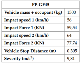
Table 2 shows the parameters used for the simulation using PLA-CF30, according to the specifications found in (Davies, 2012).
Source: Latin NCAP
Table II: Initial conditions for simulation 2

For the simulation, the UN R94 standard and frontal crash tests carried out by Latin NCAP (Latin NCAP, 2016) were considered as reference.

Figure 4: Front impact according to Latin NCAP
The deformable barrier with which the attenuator is impacted is considered a rigid wall since its behavior is irrelevant to our study. [5]
Calculating the Impact Force
To know the impact force with which the vehicle would hit at a speed of 56 km/h, we use equation 1:

Where Fm is the average force of impact; d is the average vehicle stop distance; m is the mass of the vehicle and its occupant; and v is the speed of the vehicle.

The impact force is calculated at a speed of 64 Km/h using equation 1:

In order to develop the following calculations, the impact was considered between two vehicles with similar conditions as the Latin NCAP does to perform crash tests to approximate reality. Therefore, the energy absorbed from impact was calculated with the following equations 2, 3 and 4.


Where Ec is the impact kinetic energy (J); P is the amount of movement (Kg*m/s); v 1 is the speed of vehicle 1 before impact (m/s)v 2 is the speed of vehicle 2 before impact (m/s);u1 is the speed of vehicle 1 after impact (m/s); u2 is the speed of vehicle 2 after impact (m/s).
To calculate the energy absorbed during impact, an equivalence of equation 3 was made before and after impact since momentum is preserved. For simulation purposes, it was considered a plastic impact so that the return coefficient will be 0 (see Equation 5). Po = pf

Where: m1 is the total mass for vehicle 1 (Kg), and m2 is the total mass for vehicle 2 (Kg). In addition, vehicle 2 at rest and twice as much was considered to simulate a rigid wall.

In equation 4, we replace the return coefficient value:

Finally, we replace u in equation 5:

Calculating the Energy Absorbed at 56 km/h
Replacing values in equation 6:

We calculate the kinetic energy before the shock by replacing the values in equation 2

Then, we calculate the kinetic energy after the shock by replacing the values in equation 2

And the energy absorbed is calculated using equation 7

Calculating the Energy Absorbed at 64 km/h.
Replacing values in equation 6:

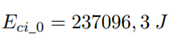
We calculate the kinetic energy before the shock by replacing the values in equation 2
Then we calculate the kinetic energy after the shock by replacing the values in equation 2

And the energy absorbed is calculated using equation 7

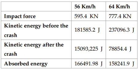
The results obtained are summarized in Table 3.
Source: own work.
Table III: Results
Simulation
To simulate the impact attenuator in the Explicit Dynamics environment, the model is imported to the IGES extension (surfaces) because it makes it easier to include the thickness value and is more compatible with the software when defining the meshing.
Once the model is exported, we used the SpaceClaim editor to open it, entered the attenuator thickness, and created the deformable barrier according to the Latin NCAP for front crashes. The created barrier will be simplified as a rigid wall (see Figure 5).

Figure 5: Creating the Barrier in SpaceClaim
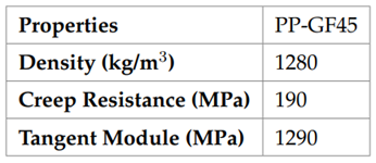
We entered the Engineering Data environment to add the PP-GF45 because it does not exist in the Ansys Workbench Explicit Materials Library. The characteristics of the material required to perform the explicit analysis are shown in Table 4.
Source: own
Table IV: Material properties PP-GF45
Then we proceeded with the meshing and performed the convergence. To do this, several meshing tests were done to find the most suitable for our analysis. Considering that processing time and mesh quality approach a value of 1 when using the Jacobian Ratio option to validate the model and obtain reliable results.

Figure 6: Mesh convergence
Once the proper meshing is selected, we defined the attenuator anchors in the holes where the clamping bolts go because the highest concentration of stress will be found on those points.

Figure 7: Anchor points
Then, the impact speed was set with values of 56 Km/h and 64 Km/h, respectively, as the initial conditions of the two simulation cases. In Analysis Settings, we selected “High Speed” because the Explicit Dynamics module considers speeds higher than 10 Km/h as “high.”
This settings were also included in Ansys for the corresponding simulation time, based on various tests performed at 0.002 seconds with a several test cycles. We also worked with the AUTODYN Standard Hourglass model, which is the most appropriate for the model to be tested because this option allows us to simulate a scenario in which the impact energy deformation of the attenuator without causing rebound.
To define the areas of distribution of the impact force, the surfaces in contact with the body supports will be taken into account since they would be the first to undergo the impact.
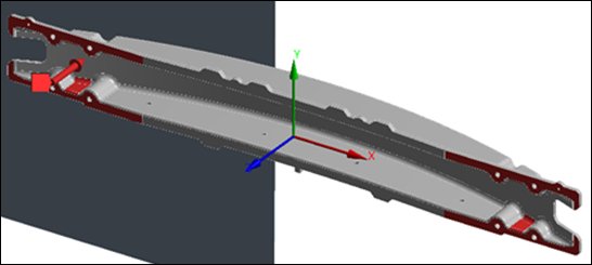
Figure 8: Distribution of impact forces
We entered the two impact units calculated in the previous section of 595.4 KN and 777.6 KN.
RESULTS
To obtain the results for this research, the following parameters were considered according to the conditions described: speed, impact force, material properties, and attenuator behavior.
Deformation Results at 56 Km/h (PP-GF45)
As shown in Figure 9, the impact attenuator has a minimum deformation of 106.77 mm and a maximum of 900.98 mm. The part that suffers the most deformation is the area around the anchors.

Figure 9: Deformation at 56 Km/h.
Deformation Results at 64 Km/h (PP-GF45)
Figure 10 shows that the minimum deformation for PP-GF45 is 153.39 mm and the maximum deformation is 1038.9 mm. As in the section above, the most deformed area is around the anchors.

Figure 10: Deformation at 64 Km/h.
Von Mises Results at 56 Km/h (PP-GF45)
As shown in Figure 11, the maximum effort is 1.045 GPa and the minimum is 0.010 GPa. The highest concentration of stress occurs around the anchors.

Figure 11: Von Mises results at 56 Km/h.
Energy Results at 56 Km/h (PP-GF45)
In Figure 12, the purple line represents the energy of the impact attenuator, and the cyan is the energy of the rigid wall. The intersection of the two lines represents the moment when the attenuator hits the rigid wall and begins to undergo physical changes.

Figure 12: Energy results at 56 Km/h.
The energy absorbed by the impact attenuator has a value of 83000 J at 55000 cycles.
Energy Results at 64 Km/h (PP-GF45)
Figure 13 shows that the energy absorbed by the impact attenuator is 113000 J at 55000 cycles.

Figure 13: Energy results at 64 Km/h.
Deformation Results at 56 Km/h (PLA-CF30)
As shown in Figure 14, the impact attenuator has a minimum deformation of 35.669 mm and a maximum of 174.09 mm.

Figure 14: Deformation of PLA-CF30 at 56 Km/h.
Deformation results at 64 km/h (PLA-CF30)
According to Figure 15, a minimum deformation of 38.78 mm and a maximum of 290.78 mm was obtained.

Figure 15: Deformation at 64 Km/h.
Von Mises Results at 56 Km/h (PLA-CF30)
As Figure 16 shows, the maximum effort is 1.345 GPa and the minimum effort is 0.023 GPa.

Figure 16: Von Mises results at 56 Km/h.
Von Mises results at 64 Km/h (PLA-CF30)
Figure 17 shows that the maximum effort is 1.339 GPa while the minimum is 0.013 GPa.

Figure 17: Von Mises results at 64 Km/h.
Energy Results at 56 Km/h (PLA-CF30)
As shown in Figure 18, the purple line indicates the energy of the impact attenuator, while the cyan is the energy of the rigid wall. The intersections of the lines occur at two points: the first represents the moment the attenuator impacts the rigid wall and the deformation process begins; the second point is the rebound of the attenuator against the rigid wall.

Figure 18: Energy results at 56 Km/h
An energy absorption value of 10000 J was obtained at 55000 cycles.
Energy Results at 64 Km/h (PLA-CF30)
According to Figure 19, an energy absorption value of 19000 J is available at 55000 cycles.

Figure 19: Energy results at 64 Km/h
Impact Test
The test method was performed according to ASTM D6110-04. Standard test method for determining Charpy impact resistance with plastic specimen notch.
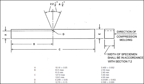
Figure 20: Standard dimensions of the impact sample.
The samples for two plastic materials were acquired: The PP-GF45 was removed from the impact attenuator of a later crashed Chevrolet Optra 1.8 vehicle, and the PLA-CF30 was obtained through 3D printing.

Figure 21: Designation of specimens
The reading obtained on the Charpy pendulum clock during the test is the energy absorbed by the specimen when broken. The results obtained from the tested materials are shown in Table 5.
Source: own
Table V: Charpy impact test results
CONCLUSIONS
By simulating the frontal impact on the Explicit Dynamics module of the Ansys Workbench software, it was possible to evaluate a virtual model of an impact attenuator by simulating the conditions under which a real head-on collision occurs. After the simulations, it is possible to conclude that the design and material designed meet the requirements for implementation on a vehicle.
After analyzing the results, it was possible to evaluate the behavior of the impact attenuator during a head-on collision. Thus, in the PP-GF45 it was observed a maximum deformation of 1038.9 mm, a maximum stress of 1.075 GPa and an energy absorption of 113000 J. According to this, the material suffers great irreparable deformations but absorbs more impact energy.
Conversely, the PLA-CF30 the following values were obtained: maximum deformation of 290.78 mm, maximum stress of 1.339 GPa and an energy absorption of 19000 J. Therefore, it can be said that the material is more resistant to deformation and stress but does not absorb too much energy.
The results obtained through the Charpy software and the impact test in the energy absorption laboratory have a consistent relationship between the two materials, so there is certainty that the results found are reliable.
References
License
Esta licencia permite a otros remezclar, adaptar y desarrollar su trabajo incluso con fines comerciales, siempre que le den crédito y concedan licencias para sus nuevas creaciones bajo los mismos términos. Esta licencia a menudo se compara con las licencias de software libre y de código abierto “copyleft”. Todos los trabajos nuevos basados en el tuyo tendrán la misma licencia, por lo que cualquier derivado también permitirá el uso comercial. Esta es la licencia utilizada por Wikipedia y se recomienda para materiales que se beneficiarían al incorporar contenido de Wikipedia y proyectos con licencias similares.