
DOI:
https://doi.org/10.14483/udistrital.jour.tecnura.2012.3.a01Published:
2012-07-01Issue:
Vol. 16 No. 33 (2012): July - SeptemberSection:
ResearchDefinición de un controlador basado en emociones para sistemas dinámicos
Definition of an emotion-based controller for dynamical systems
Downloads
How to Cite
APA
ACM
ACS
ABNT
Chicago
Harvard
IEEE
MLA
Turabian
Vancouver
Download Citation
Definition of an emotion-based controller for dynamical systems
Definición de un controlador basado en emociones para sistemas dinámicos
José Danilo Rairán Antolines
Ingeniero Eléctrico, magister en Automatización Industrial, candidato a Doctor Ingeniería de Sistemas y Computación de la Universidad Nacional de Colombia. Docente de la Universidad Distrital Francisco José de Caldas. Bogotá, Colombia. Contacto: drairan@udistrital.edu.co.
Fecha de recepción: 29 de agosto de 2011 Fecha de aceptación: 14 de febrero de 2012
Abstract
An enormous number of solutions have been proposed from the field of artificial intelligence in order to endow machines with the ability to make plans without human guidance. In this paper, we suggest emulated emotions to endow machines with the skills to make human-like decisions. The model is described using dynamical systems. Emotional states are defined in terms of the difference between a reference model and the trajectories of the system. For example, calmness is defined as the ideal emotional state, where there is agreement between the state of the system and the reference model. Finally, a basic architecture for this kind of emotional-based controller is provided together with some experimental results that illustrate its use.
Keywords:control, decision-making processes, emotions, nonlinear systems.
Resumen
Una cantidad enorme de propuestas han sido probadas, desde la inteligencia artificial, para dotar a las máquinas con la habilidad de hacer planes sin guía humana. En este artículo se sugieren emociones emuladas para dotar a las máquinas con una capacidad semejante a la de los humanos con respecto a tomar decisiones. El modelo es probado con sistemas dinámicos. Los estados emocionales son definidos de acuerdo con la diferencia entre un modelo de referencia y las trayectorias del sistema. Por ejemplo, calma se define como el estado emocional ideal, esto es, cuando las trayectorias del sistema y del modelo de referencia coinciden. Finalmente, una arquitectura básica para esta clase de controladores basados en emociones es presentada con algunos resultados experimentales que ilustran su uso.
Palabras clave: control, toma de decisiones, emociones, sistemas no lineales.
1. Introduction
Machines can not make their own plans or guide themselves, but have to be programmed. As a result, it is necessary to build redundancy into systems for protection against faulty control, because the operation of the machine could be a threat to its own integrity. Moreover, machine complexity has been increasing, but their intelligence has not evolved at a comparable pace. Some solutions have been proposed from areas such as computational intelligence, fuzzy logic, neural networks, swarm intelligence, even artificial immune systems [1]. However, we have not yet reached the ability to create models of consciousness to instill in machines the ability to decide what to do, or to set their own goals or values.
Addressing these problems in machines requires solutions from many areas of science. In this paper, we consider two sub problems, namely adaptability and autonomy. Adaptability requires the observation of two sources of information: the inside and the outside of the system. Outside information requires changes in the environment, and they can come in different degrees and rates. If they come too slowly, the machine will not notice them, but if they come too fast, the machine will not have enough time to learn them [2], [3]. On the other hand, the system could also be seen as a source of internal information, if it is able to sense itself. An autonomous system is by definition one that performs tasks in a possibly unknown environment without human supervision. This ability requires that the system make decisions to evaluate current external or internal information that defines what is desirable and what is not [4]. The primary challenge for an autonomous machine is motion planning; i.e., the ability to go from point A to point B, while avoiding obstacles in an unknown or changing environment. A solution for motion planning will determine a strategy for finding a route that is to be followed by the machine as closely as possible. In particular, the machine must adequately reference the actuators (e.g., the motors or hydraulic cylinders that make it move). This reference requires the specification of physical variables such as velocity and position, which must be set at specific values. Therefore, the machine must define how to go from an initial state to a desired final state (e.g., from rest to a given value). But again the same problem arises: the machine does not have enough intelligence to make its own decisions to follow its own paths. Therefore, solving the lower-level problem of developing intelligent controllers would appear to be a useful approach for solving the larger problem of motion planning.
One of the most adaptive and autonomous entities in nature is the human being: We move around the world, we gain experience, we learn, we make associations, and make decisions that are useful for survival and reproduction. We have thus transformed the environment to serve our purposes and plans, and reasoning is definitely one of our most powerful tools in that process. On the other hand, machines are controlled by controllers designed by engineers, through reasoning and logic, using mathematical functions and algorithms, which have proven to become difficult computing problems. Psychologists and neuroscientists have established that it is not possible to learn and reason effectively without emotions, and therefore emotions play an important role in long-term memory, learning, and decision-making [5].
In this paper, the working hypothesis is that emulating emotions as part of control algorithms would make them more adaptive and autonomous. Emotion-based algorithms would then finally be able to develop their own plans even under changing environments and without human guidance. This new type of control can be seen as the brain of an agent that moves over a landscape sculpted by the dynamics of the system in the phase plane of the controller. The controller serves as an advisor to this agent and guides it as to what to do and what the best road to reach the goal will be, as well as some set of values similar to the ones experienced by humans. The agent makes decisions based on logic and emotion in order to pursue the reference model. The agent will thus become adaptable, deal with environmental changes, and be able to address new challenges for which the agent has not originally been programmed
The organization of the paper is as follows: In Section two, a platform to define emotions is presented. In Section three, the phase plane is chosen as the mathematical tool to represent the behavior of the system. In the fourth Section, the definition of a reference model related to the emotional state is presented. In Section five, a range of emotional states is characterized, going from calmness to anger. In Section six, the controller architecture is detailed. Section seven presents some experimental results; and finally, some conclusions are presented in Section eight.
2. COMPUTATIONAL MODELS OF EMOTION
Researchers in cognitive science and related areas have proposed computational models of emotions. These are useful for demonstrating or refuting theories about emotions. One of the most complete models is based on neuroscience and addresses the interaction between attention and memory [6]. Other models are guided by the cognitive process of decision making, especially applied to robotic or virtual agents [7] - [9]. Two of them have been used in dynamical systems control, as is proposed in this paper. Although originally not designed for adaptive control, the model in [10] is relevant to this work. The authors of that paper aim at modeling the learning that happens in the human amygdala and the orbitofrontal cortex, which is related to emotional learning. Their basic equations express connections among elements, and each component works based on comparisons through four basic operations. The authors provide a helpful algorithm for actual applications.
In this section, we assume a continuous model of emotions. This means that there are theories in which emotions are discrete, so some of them become basics or principals. Due to the fact that the discrete point of view has inspired engineering applications, it is appropriate to mention some of its theorists. For instance, Robert Plutchik, Paul Ekman, and Nico Frijda, identify 8, 6, and 6 basic emotions, respectively. Concerning control, some studies based on discrete emotions make use of anger and fear in search algorithms, as well as in the generation of autonomy [11].
In contrast to the discrete theories of emotions, the continuous theories show two focuses: one known as the appraisal theory and the other as the dimensional theory of affection. Two exponents of the first proposal are psychologists Richard Lazarus and Craig Smith. They seek to define emotions as a result of the evaluation of a situation; this definition explains why the same condition activates a variety of emotions in the same person, according to the context, or different emotions in different people. A particular kind of emotion is defined by factors such as how expected the situation is, the importance of the goal, how well the system can cope with the situation, how much energy is available, and so on. Models of emotion have reportedly used anywhere between 5 and 16 variables [12]. This type of theory has recently received academic support from the field of neuroscience. It has also been complemented by the use of the nonlinear dynamical system theory, and the generation of computational models of emotion [13].
An important type of continuous models of emotion is the dimensional theory, proposed by Russell in 1980. He measured emotional states in human beings through two variables: valence and arousal [14]. Russell represented the two variables in a Cartesian coordinate system with the valence on the horizontal axis. It became apparent then that emotions occupied a circular region. This model is sometimes referred to as the circumflex model of affect. Although originated in psychology, this model has also been supported by recent research in neuroscience [15]. This model has made many contributions to medicine, psychology, language analysis, and music, among other specializations. Recent results, closely related to this paper, are a measurement of emotional states when changing screen colors of a mobile phone [16], or the changing characteristics of a video game [17]. Another contribution in robotics concerns the design and construction of a robot, EDDIE, to regulate the movement of its eyes, ears and mouth in the generation of emotional expressions [18]. These models and applications are strong evidence that dimensional theory is useful to build a control strategy based on emotions.
3. METHODOLOGY
3.1 Plant Identification
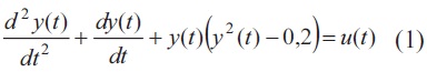
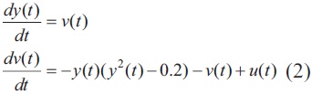
In this paper, we assume that the plant to be controlled can be described by system on nonlinear differential equations in one state variable. The basic model of such systems is the phase plane [19]. The system is usually described by two equations in two variables, the second one of which is the velocity; the other variable is the position of the system. An example is shown in Eq.(1) and Eq.(2), where "y(t)" is the output of the system, "v(t)" is the rate of change of y(t), and "u(t)" is the input.
The phase plane can be described as a vector field, as shown in Fig. 1. It associates a vector to every pair (y(t),v(t)). The horizontal component of the vector is v(t) and the vertical is dv(t)/dt, as it is described in (2). Each arrow in the vector field indicates the motion direction, so (y(t+Δt), v(t+Δt)) can be predicted by current values of y(t) and v(t). Each point in the phase plane is a description of the system at any given point in time. The dynamic of the system changes the state of the system as indicated by the arrows. The goal of the controller is to change the direction of the system through an actuating signal u(t) in order to reach a desired state. Left unperturbed, the dynamics of the system will take the plant to an attractor, or else will have a divergent behavior depending on the nature of the system. Different conditions lead the system to different attractors or global states.

If the reference does not change, the desired v(t) will be zero. The algorithm driving the control should make decisions in order to transform the current y(t) into the desired reference value yr(t), through the external intervention of the input u(t) to modify the dynamics of the system. The control algorithm therefore has only three possible decisions: increase, decrease or maintain the current value. The algorithm is complicated by the fact that it is necessary to determine when, how much and exactly how long it will take to the system to reach the target value.
3.2 The reference model
In this section we describe the reference model. The reference model should be smooth in order to avoid instantaneous changes in the state of the system. If that is not the case, a low pass filter can be used to smooth the reference r(t); such a filter will be called the reference model �(RM for short.) Otherwise, it will be assumed that the reference model meets all the technical constraints that the overall system must accomplish, including an adequate peak response, a maximum settling time, and a given rise time. There are at least two types of models that fulfill these constraints and are well established, namely Bessel and ITAE [20]. The first one has zero overshoot, and the second one is optimal in energy consumption. Once the model has been selected, there only remains to determine the settling time.
A reference model (RM) is an important component of the controller, because it produces smooth transitions, and also "teaches" the system how to "behave". The RM is the mentor, and everything is measured according to its behavior with respect to the target. Fig. 2 shows an unstable system which becomes stable when it follows the RM. In this example, a classical PI controller uses the distance between y(t) and RM output, and feeds the input signal to the system proportionally.
It appears that the system is on pursuit of the reference model. The reference model knows the location of the target value, namely the reference point, while the system is on pursuit of the RM. In this sense, a perfect controller is one that leads the system to stay just one step behind RM. Therefore the dynamic of the system has changed from trying to reach an attractor to reaching the reference points and having the same dynamic as the RM. In the example shown in Fig. 2, RM is 1/(S2 + S + 1), and the system is 1/(S � 1). In addition, a unitary feedback is used, as well as a classical PI controller with P = 2, I = 2.

Pursuit-evasion strategies have served as inspiration for solving problems about evolutionary computing, network security, motion planning, cooperative robotics, and many others [21], [22]. In our case, there is a huge simplification in the evader's behavior. It does not try to slip away, but, on the contrary, seeks the reference point, while is the "mentor" for the dynamical system, which follows it.
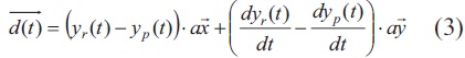
Once the continuous nature of the process is defined by (1) and (2), it makes sense to choose a geometric approach to measure the distance from the system to the RM. Fig. 3 shows a snapshot of the dynamic at a certain time t. Ideally, the system should move towards the RM values along the line of sight between RM and the system's current state. The system in Fig. 3 is described by coordinates (yp(t),dyp(t)/dt), while RM represents the ideal output at every time t, with position yr(t) and speed dyr(t)/dt.

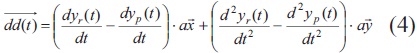
The vector d(t) is defined in Eq.(3). It is the difference between the position vector of RM and the system behavior in the phase plane. The ideal magnitude for d(t) is zero, and the way to assess how much it should increase or decrease is by computing a second vector dd(t), given by Eq.(4).
Now, corresponding unit vectors Ud(t) and Udd(t) are computed to simplify future analysis, because d(t) and dd(t) have different units and they are used only to compare directions. For instance an ideal situation happens when d(t) decreases, so that dd(t) has exactly the opposite direction to that of d(t), regardless of their magnitude. This is why d(t) is multiplied by -1 in Eq.(5). Therefore, the goal of the controller is to bring the system to having zero angle between -d(t) and dd(t).

In the best case, this angle is zero. In the worst case the angle is p rad. This angle is defined in Eq.(7), and it is at the heart of the control algorithm described next

3.3 The emotion model
In this section, we define a model of emotion as mentioned above; the ideal emotional state to solve hard problems is calmness. Generally, complex tasks will require lower emotional arousal in order to get an equivalent performance than a simple task. This fact is known as the Yerkes-Dodson law [23]. Therefore, the ideal situation (a = 0) can be labeled calmness. This ideal can be used by a new algorithm to avoid other emotional states.
Since it would be too ambitious to attempt to define at first a model with the full range of emotions as they can be felt by humans, we will simply define an adequate subset that helps to perform control tasks. In particular, emotional disorders such as stress, phobias, manias, and so on will be excluded. Likewise, more complicated behaviors such as experiencing several emotions at the same time, or mixing them up, will be excluded.
One way to visualize the emotional state of the controller is to imagine them as being experienced by a person carrying out the same control task. The person may experience happiness when encountering positive results after experiencing challenges; on the other hand, the person can experience fear or anger with the opposite outcome. These emotions can be characterized in terms of the angle a as shown in Table 1. For simplicity, we are assuming that the emotional state of the controller depends exclusively on the value of a. Previous values or future values are not considered.

3.4 Control Architecture
The next step is to specify an algorithm for the emotion-based controller. The emotions are the values of α as given by inputs to the controller. This single number represents the state of the system at the given time that can be used to make decisions. Those decisions are externalized by means of an actuating signal u(t), which drives the system to follow a desired behavior.
The goal of this section is to describe in detail the emotional component of the controller, as shown in Fig. 4. The model includes an additional variable called mood. Mood is defined in psychology as the fixation of an emotion that has been felt for a period of time. For instance, if the mood is anger, it can turn gradually from negative to positive after experiencing a positive emotion for some time. A simplified way to implement a mood module in our model is by means of a low pass filter. The mood module uses α to stabilize possible fluctuations of the system, especially when they are caused by noise or faults.

The emotional controller also includes a numerical integrator, which sums up the emotion and mood outputs. The output of the integrator is UE in Fig. 4. Calmness is associated with ue equal to zero, while anger is associated with the maximum value ue, as described below. If the emotion is calmness, the integral holds UE on the previous value, which makes sense, because the decision is to feed the plant using an actuating signal that has proved effective in leading the system to a desired dynamic. When the emotion is different from calmness, ue is different from zero and the output of the integral increases or decreases, according to the emotion, changing the value of u(t) fed into the system in order to compensate for any deviation from the reference model.
The last component of the architecture is a traditional controller, for example a PID, as shown in Fig. 4. It makes decisions to regulate a system based on the difference between the reference, yr(t), and the output, yp(t). That process is referred to as "logic" in this paper. The mixture of logic and emotion is a powerful tool to define the actuating signal by means of adapting decisions, according to the dynamics of the plant. The relationship between the logical and emotional components can be as simple as an additive algorithm, as shown in Fig. 4. However, that control can make more sophisticated choices and be replaced by a soft algorithm, such as a fuzzy system.
4. RESULTS
In this section, we present several results of the model in Fig. 4. The emotion model computes two values: α and ue, where ue is the decision made by the controller in order to keep the system within limits and constraints. The simplest type of computation is to multiply α by a constant to obtain ue. That constant could be, for instance, a positive number. Unfortunately, kemα is not enough to control every dynamical system, because the value of α does not capture how far the system is from its goal. One way to overcome this problem in our first example is by changing the intensity of the emotion proportionally to the difference yp(t) - yr(t). In the ulterior examples it is to multiply kemα by the sign of the difference between these two values.
The results of the simulation of this model on a first order system are shown in Fig. 5. The figure shows the comparison between the performance of the emotion based controller in reference to the traditional PID controller under the following parameters:
- Plant: H(S) = 1/ (S � 1)
- RM(S) = 25/(S2 + 10S + 25)
- Kp = 7, Ki = 10, and Kd = 1
- The feedback has unitary gain
- Null Initial conditions
- kem = 7e3
- Simulink is configured to solve using variable-step, the maximum step size is 0,5e-2 s, and the relative tolerance is 1e-3.
The result is remarkable: the emotional controller produces a maximum error of 5e-3, while the PID controller shows an error of 0,3. However, this performance cannot be generalized to second or higher order systems.

The next example illustrates how calmness is not a guaranty of none error, but a condition of the controller seeking to shrink this value to zero, as illustrated in Figure 6 at t = 4 s.
Parameters for simulation in Fig. 6 are:
- H(s) = 1/(S+ 1)
- RM(S) = 1/(S2 + S + 1)
- Kem = 5
- The feedback has unitary gain
- Null Initial conditions
- step size for the solver in Simulink = 5e-3 s.

The third example illustrates the control over a second order system, as shown in Fig. 7. The maximum error for the emotion based controller is 6e-3, which is 30 times smaller than maximum PID error. The parameters of the simulation are:
- H(S) = 1/(S2 + 2S + 1)
- RM (S) = 4/(S2 + 2S + 4)
- Kp = 5, Ki = 5, Kd = 1
- kem = 1e4
- The feedback has unitary gain
- Null Initial conditions
- Simulink is configured to solve using fixed-step at 1/800 s.

The last example shows the performance of the control on a nonlinear dynamical system, as shown in Fig. 8. This is a discrete system with dead zone and noise. The initial output of the plant is different from the initial condition of the RM, which makes the problem even harder. The RM is 4/(S2 + 2S + 4). In addition, Simulink is configured to run using a fixed-step of 1/800 s. Finally, kem = 1e3.

5. DISCUSSION AND CONCLUSIONS
The architecture of an emotion-based controller has been defined in this paper. The use of the model has been illustrated with first and second order linear and nonlinear dynamical systems. The model includes two novel modules, named emotion and mood, and it could be extended to include a traditional controller. The primary component of the emotional-based controller is an angle α, associated with the distance between the plant dynamic value and the reference model output. This is akin to the difference between expected current scenarios triggering emotions in humans. Zero angle is associated with calm, while the value of π is associated with anger. The heuristics of the model follows well known facts in psychology that the ideal emotional state is calmness. Therefore in the model, when that emotion is "felt", the best decision of the controller is to leave the actuating signal of the controller unchanged. In the model, the system explores its phase space (landscape) in pursuit of the reference model, which at the same time pursues the set point. The strategy is consistent with the Circumplex Model of Affect for human emotions.
Four examples of application have been presented. They show that the representation of the human emotions is useful to improve the performance of controllers. These examples show that these modules help control unstable and stable first order linear systems, as well as linear and nonlinear second order systems.
References
[1] R. Canham, A.H, Jackson, and A. Tyrrell, "Robot error detection using an artificial immune system", in Evolvable Hardware, Proceedings. NASA/DoD Conference, July, 2003, pp. 199�207.
[2] D. Gomez, "Comparison of Frequency Response and Neural Network Techniques for System Identification of an Actively Controlled Structure", Dyna Journal, No. 170, December, pp. 79-89, D2011.
[3] S. Oviedo, J. Quiroga, J. and C. Borrás, "Motor Current Signature Analysis and Negative Sequence Current Based Stator Winding Short Fault Detection in an Induction Motor", Dyna Journal, No. 170, December, pp. 214�220, 2011.
[4] D.N. Davis, and S.J. Lewis, "Computational Models of Emotion for Autonomy and Reasoning", Informatica, Special Edition on Perception and Emotion Based Reasoning, Vol. 27, No. 2, June, pp. 159�165, 2003.
[5] A. Damacio, Descartes' error: Emotion, Reason, and Human Brain, Ed. Penguin Books: USA, 1994.
[6] N. Fragopanagos, and J. Taylor, Modelling the interaction of attention and emotion, in Neurocomputing, No. 69, 2006, pp. 1977�1983.
[7] K. Gurney, T.J. Prescott, and P. Redgrave, "A computational model of action selection in the basal ganglia. II. Analysis and simulation of bahaviour", Biological Cybernetics, No. 84, pp. 411�423, 2001.
[8] R. Marinier and J. Laird, "Towards a Comprehensive Computational Model of Emotions and Feelings", in 6th International Conference on Cognitive Modeling, pp. 1�6, 2004.
[9] F. Michaud, "EMIB � Computational Architecture Based on Emotion and Motivation for Intentional Selection and Configuration of Behaviour-Producing Modules", in Cognitive Science Quarterly, Cognitive Science Quarterly, Special Issue on Desires, Goals, Intentions, and Values: Computational Architectures, pp. 1�20, 2002.
[10] J. Morén, and C. Balkenius, "A Computational Model of Emotional Learning in the Amygdala", in MIT Press, Proceedings of the 6th International Conference on the Simulation of Adaptive Behavior, pp. 1�9, 2000.
[11] L. Cañamero, "Designing Emotions for Activity Selection in Autonomous Agents", in Emotions in Humans and Artifacts, Cambridge, MA: The MIT Press, pp. 115�148, 2003.
[12] R. Marinier, and J. Laird, "Computational Modeling of Mood and Feeling from Emotion", in CogSci, pp. 461�466, 2007.
[13] D. Sander, D. Grandjean, and K. Scherer, "A systems approach to appraisal mechanisms in emotion", in Neural Networks, Science Direct, No. 18, pp. 317�352, 2005.
[14] J. Russell and F. Barrett, "Core Affect, Prototypical Emotional Episodes, and Other Things Called Emotion: Dissecting the Elephant", Journal of Personality and Social Psychology, No. 76, Vol. 5, pp. 805�819, 1999.
[15] J. Posner, J. Russell, and B. Peterson, "The circumplex model of affect: An integrative approach to affective neuroscience, cognitive development, and psychopathology", Development and Psychopathology, No. 17, pp. 715�734, 2005.
[16] P. Fagerberg, A. St�hl, and K. Höök, "eMoto: emotionally engaging interaction", in Personal and Ubiquitous Computing, No. 8, pp. 377�381, 2004.
[17] C. Peter and A. Herbon, "Emotion representation and physiology assignments in digital systems", in Interacting with Computers, No. 18, pp. 139�170, 2006.
[18] S. Sosnowski, K. Kühnlenz, K. and M. Buss, "EDDIE - An Emotion-Display with Dynamic Intuitive Expressions", in The 15th IEEE International Symposium on Robot and Human Interactive Communication, September, pp. 569�574, 2006.
[19] X. Gai, S. Liu and N. Zhang, "Research of a new type intelligent controller and its application", in Intelligent Control and Automation, 2008. WCICA 2008, 7th World Congress, June, pp. 760�764, 2008.
[20] A. Marshak, D. Johnson and J. Johnson, "A Bessel Rational filter, in Circuits and Systems", IEEE Transactions, No. 21, Vol. 6, November, pp. 97�799, 1974.
[21] Y. Chen, H. Qi and X. Liu, "Mas-Based Pursuit-Evasion Algorithm Under Unknown Environment", in Machine Learning and Cybernetics, Proceedings of 2005 International Conference, Vol. 1, August, pp. 265�269, 2005.
[22] N. Karnad, and V. Isler, "Bearing-only pursuit", in Robotics and Automation, ICRA 2008. IEEE International Conference, May, pp. 2665�2670, 2008.
[23] B.F. Gore and P. Jarvis, "Modeling the complexities of human performance", in Systems, Man and Cybernetics, 2005 IEEE International Conference, Vol. 2, October, pp. 1604�1609, 2005.
License
Esta licencia permite a otros remezclar, adaptar y desarrollar su trabajo incluso con fines comerciales, siempre que le den crédito y concedan licencias para sus nuevas creaciones bajo los mismos términos. Esta licencia a menudo se compara con las licencias de software libre y de código abierto “copyleft”. Todos los trabajos nuevos basados en el tuyo tendrán la misma licencia, por lo que cualquier derivado también permitirá el uso comercial. Esta es la licencia utilizada por Wikipedia y se recomienda para materiales que se beneficiarían al incorporar contenido de Wikipedia y proyectos con licencias similares.