
DOI:
https://doi.org/10.14483/udistrital.jour.tecnura.2014.2.a10Publicado:
01-04-2014Número:
Vol. 18 Núm. 40 (2014): Abril - JunioSección:
RevisiónIntroducción breve a la ingeniería dirigida por modelos
A brief introduction to model-driven engineering
Descargas
Cómo citar
APA
ACM
ACS
ABNT
Chicago
Harvard
IEEE
MLA
Turabian
Vancouver
Descargar cita
A brief introduction to model-driven engineering
Introducción breve a la ingeniería dirigida por modelos
Vicente García Díaz1, Edward Rolando Nüñez Valdez2, Jordán Pascual Espada3, B. Cristina Pelayo García Bustelo4, Juan Manuel Cueva Lovelle5, Carlos Enrique Montenegro Marín6
1Engineer Informatic and Doctor in Computer Science. Researcher in University of Oviedo, Spain. Contact: garciavicente@uniovi.es
2Engineer Informatic and Doctor in Computer Science. Researcher in University of Oviedo, Spain. Contact: nunezedward@uniovi.es
3Engineer Informatic and Doctor in Computer Science. Researcher in University of Oviedo, Spain. Contact: pascualjordan@uniovi.es
4Engineer Informatic and Doctor in Computer Science. Researcher in University of Oviedo, Spain. Contact: crispelayo@uniovi.es
5Engineer Informatic and Doctor in Computer Science. Researcher in University of Oviedo, Spain. Contact: cueva@uniovi.es
6Engineer Informatic and Doctor in Computer Science. Researcher in Universidad Distrital "Francisco José de Caldas", Colombia. Contact: cemontenegrom@udistrital.edu.co
Fecha de recepción: 18 de mayo de 2013-Fecha de aceptación: 27 de agosto de 2013
Clasificación del artículo: revisión
Financiamiento: Universidad de Oviedo
Abstract
The software crisis is a concept that has started to be used in 1968, at the first conference organized by the North Atlantic Treaty Organization (NATO) on software development. There, Edsger Dijkstra criticized that projects were not completed in compliance with the classic triple constraint of project management (scope, time and cost), since most of them do not reach the expected requirements, are delivered out of time or exceeds the expected cost. Unfortunately, the current reality is that while there have been proposed new methodologies aimed at solving the usual problems related to software development, there is still no reliable method to estimate the development of computer systems. This work introduces the Model-Driven Engineering approach that, according to the experts, will help to solve many of the problems that thousands of software development teams have daily worldwide.
Key words: Development, Domain-Specific Languages, Languages, Meta-Metamodel, Metamodel, Model-Driven Development, Model-Driven Engineering, Model, Models, Software.
Resumen
La crisis del software es un concepto que comenzó a utilizarse en 1968, en la primera conferencia organizada por la Organización del Tratado del Atlántico Norte (OTAN) en el desarrollo de software. Allí, Edsger Dijkstra criticó que los proyectos no se completaban debido a la clásica triple restricción de la gestión de proyectos -alcance, tiempo y costo-, ya que la mayoría de ellos no alcanzaban los requisitos previstos, se entregaban fuera de plazo o superaban el costo esperado. Por desgracia, la realidad actual es que; si bien se han propuesto nuevas metodologías destinadas a la solución de los problemas habituales relacionados con el desarrollo de software, todavía no existe un método fiable para estimar el desarrollo de los sistemas informáticos. En este artículo se presenta el enfoque de Ingeniería Dirigida por Modelos que, según los expertos, ayudará a resolver muchos de los problemas que miles de equipos de desarrollo de software tienen a diario en todo el mundo.
Palabras clave: desarrollo, desarrollo dirigido por modelos, ingeniería dirigida por modelos, lenguajes de dominio especifico, meta-metamodelo, metamodelo, modelo, modelos, software.
Introduction
The increasing complexity of software development (Royce, 1970) is becoming a more important problem. It is mainly because customers and/ or end users demand progressively more sophisticated software, with fewer errors, with more capacities and shorter development cycles (Groth, 2004) -last generation video games (Aguaded-Gómez, 2011) or systems capable of maintaining or managing multinational companies with thousands of employees (Roche, 1992)-.
Additionally, due to its rapid expansion, computer systems have become necessary and customary in almost all domains or professional areas that currently exist (Butler, 2006). This fact, although it is very positive from the economic point of view, can create certain problems such as development teams become experts in a particular field and later have to make another project in another different area, with the consequent adjustment period needed. In addition, there are many technological platforms, which mean that companies have to find experts on a specific platform o even people who can be adapted to develop software for different platforms, requiring time to learn and manage properly. All this, suggests that the development could be much more optimized if we can reuse not only part of the code that is generated daily for the different platforms, but also reuse the expertise in a concrete domain, and not only the personal experience, it would be interesting to incorporate the expertise that others have being acquired in the domain during the past of time (Caldiera and Victor, 1991).
Thus, to perform the increasingly complex software development challenges, we can consider hiring more staff. However, much better than increasing the number of developers, would be to increase the production capacity through the industrialization of software, an idea that has been around since 1968 (Mcilroy, 1968), exactly the same way other sectors have done. For example, the automotive sector, which has gone from producing cars using traditional methods to making cars in an automated way because of people like Henry Ford and his famous Ford Model T, which dates from 1908.
Nevertheless, the software engineering continually offers new tools that, used properly, can assist in the difficult task of developing effective and efficient software. Thus, during the last few years, it has appeared a new approach for software development called Model-Driven Engineering (MDE) (Kent, 2002), which raises the level of abstraction of the traditional languages through the use of models, allowing the use of concepts closer to the domain of problems.
The evolution of MDE is, from the point of view of the leading experts in the area, one of the keys to guide the way forward for the software development in the coming years. Thus, the remainder of this document shows the most important and basic aspects concerning MDE. This paper gives an overview of model-driven engineering, stating the origin through applications in business and the main underlying concepts used to perform software development projects following its principles.
The Traditional Problematic In Software Development
Enterprise applications have always been prone to problems during their development (Dijkstra, 1972). Below is a list of common problems, list that has not changed over the years, and that is the main motivation of the emergence of MDE:
- Generally, there is a poor quality in the software developed (Kan, 2002).
- Software does not meet the specifications (Jones, 2006).
- Projects conform neither to the schedule nor to the budget (Putnam and Ware, 1991).
- Maintenance becomes expensive when the project grows in size (Banker et al., 1993).
Possible causes of the above problems could include isolated development, monolithic software, low level abstraction languages, immature software development processes and increasing demand for software in society (Greenfield, 2004).
Need for automation in software development
The way to avoid the above and other problems is automating software development as much as possible. It can be said that the change has not been yet done in the computer science field, but is gradually taking steps such as the appearance of design patterns (Gamma et al., 1995), specifications, standards (Petrie, 1998), frameworks (Johnson, 1997) and languages, allowing among other things:
- Partially automate the development process.
- Find the best ways to solve the problems usually faced by developers.
- Search for homogenous ways to perform tasks in order to improve the maintenance and the interoperability of applications.
At first glance it may seem simple: a software project begins when someone has a problem and it is necessary to solve it. It needs to capture what the customer needs and implement it.
What happen most often? The customer indicates his wishes and the person in charge of collecting the specifications to implement them does not use a formal language, but even though the software systems are implemented and carried out.
What would be the most convenient? It should be interesting to use some formal language to properly collect the customer specifications as a potential early stage in the development and the automation. For this purpose software models are used.
Levels of abstraction in software development
The emergence of software models is inevitably linked to the different generations that have emerged over the years in terms of programming languages, these generations are: first generation languages -machine language-, second generation languages -assembly language-, third generation languages -procedural languages-, fourth generation languages -object-oriented languages-, fifth generation languages -aspect oriented languages- (Elrad et al., 2001).
At this point, we could talk about a sixth generation of programming languages, programming languages based on software models. However, this idea can be understood more easily from another classification, based on the level of abstraction of languages. For this purpose, some levels have been classified:
- Languages of low level abstraction
They include machine and assembly language. They are very close to the way computers work because they work directly with the hardware, hence their low level of abstraction.
•Languages of middle level abstraction
They are halfway between the low level and the high level of abstraction languages. For example, the C language can perform low level operations like working with the system registers but it can also carry on other tasks of higher level by using more complex constructors.
•Languages of high level abstraction
They are hardware independent languages and thus can be migrated from one machine to another easily by using translators and interpreters. Through these languages, there is no need for knowing the internals of the machine with which we are working. The most popular languages nowadays as C# or Java have a high level of abstraction design. The key is to use concepts closer to the problems -e.g., a Car class for working with cars- and avoid, as far as possible, using terms related to computers which have a too low level of abstraction.
The more level of abstraction there is, the more productivity we have. That is so because, in addition to use terms much closer to the way humans communicate among themselves, it is possible to use more sophisticated instructions. The last major leap that increases the productivity and the quality of software development, thus raising the level of abstraction, is the appearance of MDE, also known as Model-Driven Development (MDD) or Model-Driven Software Development (MDSD). It is considered a new paradigm in the field of software engineering. It is based on the separation of the system functionality being developed and the implementation of such a system for one specific platform, i.e., we seek to clearly separate the analysis from the implementation details. To achieve that, different software models are used.
According to Selic (2008), they are two types of complexities in the software development process: essential complexity, innevitable and due to the problem to be solved, and arbitrary complexity, due to the tools and methods used during development. MDE serves to alleviate the arbitrary complexity, rising the level of abstraction and avoiding lexical, syntactic and semantic problems with the different programming languages that exist and will exist in the future. A key point is that increasing the level of abstraction through the use of models, we can collect the specifications of the customers using a formal language.
Models And Diagrams For Software Construction
The word model has several meanings, among which can be highlighted the following:
- Set of extracts of a system under study (Seidewitz, 2003).
- Simplification of reality (Selic, 2003).
- Set of formal elements which describe something that is being developed for a specific purpose and can be analyzed using variousmethods (Mellor et al., 2003).
It could be said that models have historically been used to represent and validate systems before the superior effort involved in making the entire system directly. Examples of models can be the plans of a building or a car design prototype. As desirable features of models (Selic, 2003), the following can be highlighted:
- Cheap. It seems logical to think that the main feature that models should have is that they are much cheaper than the systems they represent, both in economic terms and in the time necessary to build them.
- Accurate. Models should represent correctly and precisely the real systems, because otherwise they would be worthless.
- Comprehensible. Obviously, a model is useless if it is expressed or represented in a confusing or difficult to understand way for those who should use it.
Regarding software, there is much confusion about the difference between a model and a diagram; therefore the two concepts are often used interchangeably, when in fact they do not mean the same. A model is a system abstraction of the real world that captures a view (a system can have multiple views). So, the model describes conceptually those aspects of the system that are relevant from their point of view, with an appropriate level of detail. A diagram, on the other hand, is a graphical representation of a collection of modeling elements; very frequently depicted as a graph. A very well-known example of diagram is the class diagram of the Unified Modeling Language (UML) (OMG, 2010), used to graphically represent the concepts of the class model -classes, inheritance, attributes, etc.-, capturing the static view of a software system. According the experience of others authors as (Seidewitz, 2003), one can say that main goal of MDE is to develop software based on models.
Basic concepts on model-driven Development
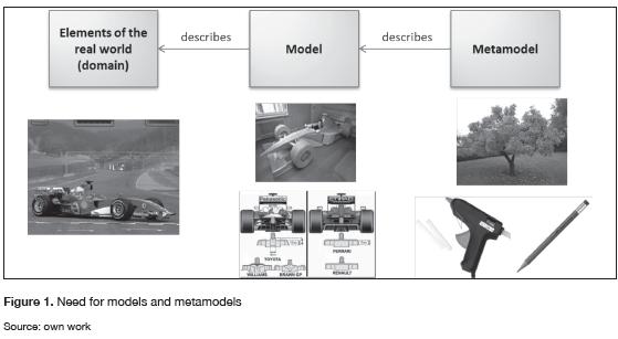
A key concept to work with models is the metamodel. Figure 1 shows an example. We can create a model of a formula 1 through different techniques -e.g., a prototype, a plan, etc.-. Such a model will represent a real world element -in this case a F1-. Typically these two ideas would be enough but from the theoretical and practical point of view of MDE, it is necessary to discuss the concept of metamodel. How we can build models? The answer is that we need other items, with a higher level of abstraction that are basic building blocks to create models. For example, to create a wooden model we would need trees, screws, power tools, etc. The peculiarity of all these elements is that they would be placed at the metamodel level and they serve to create not only the model of a F1, but many other models -that is, other prototype models in this case-.
The idea of the need of a metamodel is not recent. In (Kotteman and Konsynski, 1984) it is shown that at least there are necessary four levels of instantiation to integrate the modeling into the evolution of the computer science systems (figure 2). In fact, MDE is based on the four-layer architecture defined by the Object Management Group (OMG) (OMG, 1989).
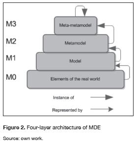
Figure 3, shows the four-layer architecture (or levels) that are used as a reference in the MDE context:
- M3 level (Meta-metamodel). The M3 level defines the concepts, the attributes and the relationships for the elements at level M2, whereas the elements placed at level M2 are the instances of the elements at level M3. In this level, OMG has defined a language that is used to describe all the elements at level M2, called Meta-Object Facility (MOF) (OMG, 2011). It can be said that MOF is the standard used as the root of all the model-driven developments.
- M2 level (Metamodel). In this level there are defined the elements of the model at level M1. In the case of a metamodel such as UML (OMG, 2010), it is possible to cite examples of concepts that are in this level as 'Class', 'Attribute' or 'Association'. The level M2 defines the valid elements in a specfic model at level M1, whereas the elements placed at level M1 are the instances of the elements at level M2.
- M1 level (Model). In this level there are defined, for instance, concepts as 'Client', 'Purchase' and 'Book' and their attributes 'Direction', 'Name', 'Number', 'Title', etc. The M1 level defines the classifications of the elements at level M0, whereas elements placed at level M0 are the instances of elements at level M1. An example in this level would be a class or a use case model.
- M0 level (Reality). There are two different approaches to describe this level. The most common is that in this level there are instances of models of M1, as for example 'Car' objects instantiated using a programming language. The other approach, the newest, states that 'Car' objects are not instances, but elements, cars in this case, of the real world (Atkinson and Kühnes, 2003).
Modeling spaces
Any element can be taken as a model if it is an abstraction of the real world. For example, a hotel prototype represents a hotel; therefore the prototype is a model. Considering the layered architecture defined by OMG, the elements used to create the prototype such as wood or glue would be the metamodel and the elements used to create the wood or the glue would form the meta-metamodel. In this case, the meta-metamodel is also called the super-metamodel (Gasevic et al., 2006) because it is the highest layer of the architecture. However, other architecture may have a greater number of levels.
In fact, UML was initially a super-metamodel but to create other metamodels compatible with each other, it was necessary to place MOF above UML. We have also to take into account that the prototype model may be an element of the real world because it can be touched, but still its role in the four-layer architecture of this example is to be the model of a hotel (its role depends on the context).
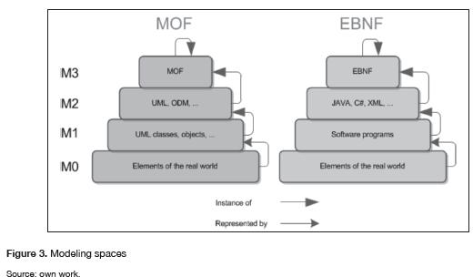
It can be said that a model represents real world things because it acts on their behalf and a model conforms to a metamodel because the metamodel defines how a model can be. A modeling space (MS) is any modeling architecture based on a super-metamodel. Figure 3 shows only two examples, but there would be so many examples as one can imagine.
The most typical example is the MOF MS, in which MOF is used as the super-metamodel. Below MOF would be, among others, UML and the Ontology Definition Metamodel (ODM) (OMG, 2009), and below them would be respectively UML models and ODM models. MOF is the standard meta-metamodel of the software industry with respect to the model-driven engineering. Note that there are so many tools to create create metamodels under the MOF guidelines. Such metamodels are the basis for working under the MDE approach.
Another example, different from the standard, could be to use the Extended Backus Naur Form (EBNF) (Essalmi and Ayed, 2006) as a super-metamodel to define context-free grammars. Below EBNF would be the different languages such as Java, Visual Basic, C, C++, C# or XML, and in the M1 layer there would be the software programs that are the models of the reality represented in that particular modeling space.
Conceptual Space
Figure 4 shows the most important and basic concepts with respect to MDE.
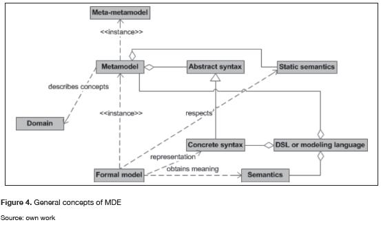
Domain
To work with MDE it is necessary to always fix a specific domain, which delimits a field of knowledge. That is the reason why it could be desirable to create an ontology of the domain concepts. There are two types of domains: technological domains, concerning the development of software technology (e.g., ASP.NET, Java, PHP) and professional domains, concerning the concepts that the application will handle (e.g., a management application, an e-commerce Website, etc.). The domains can be subdivided into smaller domains.
Metamodel
The metamodel is used to describe, in a computer environment and in a formal way, the most relevant concepts that the domain have. Furthermore, it is essential to automate the software development (Frankel, 2003).
Meta-metamodel
For metamodels to be reusable, interoperable and portable there must be another metamodel in a higher level of abstraction, uniquely describing the concepts used to represent any metamodel in any domain. The meta-metamodel is the component that performs this function. It has the peculiarity that it defines itself.
Abstract and concrete syntaxes
The metamodels are composed of an abstract syntax and a static semantics. The abstract syntax focused on the conceptual elements whereas the concrete syntax focuses on how to represent the concepts. From that it can be deduced that a metamodel would have one (or more) invariant abstract syntaxes but there would be some concrete syntaxes to represent the same concepts.
The abstract syntax of a language specifies its structure, i.e., the constructors, their properties and the connectors that such a language may have. Generally, there are also defined language rules in the metamodel, avoiding the wrong practice of code generators having to validate the models. This is because if anomalies are detected first, it will be easy to perform the task of other components.
The concrete syntax of a language is needed to define the specific notation which will be used for users of the language. Ideally, each domain and language concept is mapped to a specific notation. For example, it could be possible to use a graphical notation (like UML) or a textual notation (like Java).
Static semantics
The static semantics of metamodels are based on the abstract syntax and its mission is to make semantics checks on models to ensure they are well constructed.
Domain-specific language
A domain-specific language (DSLs) (van Deurs-en et al., 2000) is meant to express adequately the concepts of a domain. It consists of one or several metamodels -usually one-, one o more concrete syxtaxes -typically one-, and often a tool that supports it to enhance usability. A DSL is simply a defined language used specifically to address a specific problem in a concrete domain, being the key to any domain specific solution. The DSLs are often called modeling languages.
Formal model
With all the infrastructure defined so far, we can talk about formal models, which are the starting point from which it is possible to automate transformations to entities of lower level of abstraction -e.g., from a model we could automatically generate an application developed in C#-. Formal models are instances of the metamodels and are represented by a concrete syntax. Moreover, they also have to respect the static semantics that the metamodel has to perform coherent structures within a domain of knowledge.
Semantics of the problem space
The semantics of a DSL refers to all the concepts of a model, which have a meaning because every time an item is included in a model, what we are doing in reality is enriching it semantically. Unlike what happens with general purpose languages, through the use of DSLs we can map the concepts of a language directly to concepts of the domain that is being modeling, without the possibility of misinterpretation. The semantics of a DSL should be well documented or be intuitive enough for creators of models to know what concepts they are using in the problem space. That is, it is important to associate the elements of a language with the corresponding domain concepts.
Domain-Specific Modeling
When there is some experience in software development, it is easily observed that many problems encountered during development arise repetitively. Furthermore, in many times, such problems are related to a concrete domain of knowledge. To give solution to those concrete problems, it is commonly used a General Purpose Language (GPL) such as Java or C, or it can be used a DSL.
Fundamentals of domain-specific modelling
From the concept of DSL (van Deursen, 1997), we can also talk about Domain-Specific Modeling (DSM), which has its origin in the existence of many similar software developments for the same domain of knowledge, that have a common part and a variable part -sometimes the common part does not exist-. The common part can be developed using traditional development techniques and the variable part could be created using a DSL designed for a specific domain, thereby increasing the productivity. An example could be food traceability applications, in which all could share a commmon execution engine and a single database, but should be adapted to the manufacturing process of different foods like cheeses or meats. If the variable portion of the software is based only on the different manufacturing processes, it might be appropriate to create DSL to define them.
Both the concepts of DSM and DSL are essential to work with MDE. The basic idea is to create languages especially designed to solve a problem in a very specific domain, allowing language constructs to be very close to the concepts of the domain. To unify the common and the variable features of the software, there are two possible approaches:
- Interpretative. The common part has an interpreter to process the variable items. Thus, flexibility is achieved but it has drawbacks such as the obvious loss of performance and the difficulty to debug applications.
- Generative. The common and the variable parts are compiled together to build the solution as a whole. It is more complex to be done but it avoids the disadvantages of the interpretative approach.
Note that it is not always necessary to work with a fixed and a non-fixed part. It is possible that some tools can generate software ready to be used without the need of any additional element.
Classification of the domain-specific languages
There are some classifications to organize DSLs regarding their properties, emphasizing the two which are presented below:
From the point of view of managing the language
According the management of the language, it is possible to work with textual and graphical languages. Most computer languages are textual and are composed of an ordered set of sentences. A very well-known example is the Structured Query Language (SQL) (Date and Hugh, 1987) to work with databases. It could be possible to create textual DSLs in several ways. The first one would consist on building a grammar, for example using the Backus-Naur Formalism (BNF) (Knuth, 1964) for the language and then creating or using a parser for the grammar -Yacc (Johnson, 1975), Bison (Donnelly and Stallman, 1992) or Antlr (Parr, 2007) are tools that serve to generate a parser- with the difficulty that this implies. Another simple way to create a DSL may be using a XML, with the consequent syntactic limitation but with the advantage of the existence of a large number of tools for working with XML. What really matters if we want to work with MDE is that the DSL should be based on a formal metamodel.
In recent years, graphical languages are gaining wide acceptance. As an example we can cite UML. Creating a graphical language can be considered analogous to creating a textual language, with the difference that instead of working directly with text, it is necessary to create mappings from the graphical notation. Almost all the graphical DSLs have a notation consisting of several connectors and simple shapes that are the basis for creating more complex elements. A graphical DSL has a metamodel composed of classes that represent a concept of the domain -typically mapped as figures in their diagrammatic representations-, and relations among classes -typically mapped as connectors-. There will also have constraints used to check if the diagrams that represent the models are valid. Another important concept is serialization, which is necessary to keep all the elements of the diagrams in a persistent way, being advisable to do that in a format that promotes interoperability as XML.We should add that works like (Tolvanen, 2008) mention the existence of other types of DSLs, such as the mix between graphical and textual notations, tables, forms, trees, etc.
From the point of view of the domain problem
According to the point of view of the domain problem, languages are classified into horizontal and vertical types:
Horizontal DSLs are used when the customer that will use the software does not belong to a specific industrial sector. An example is a DSL to generate user interfaces in desktop applications such as Windows Forms in the Visual Studio development environment.
Unlike with horizontal DSLs, customers that use vertical DSLs belong to the same industrial sector. An example may be a hypothetical DSL to build the variable part of the food traceability software discussed above.
Requirements of a domain-specific language
There are several requirements that are necessary (Kolovos et al., 2006) to build a DSL.
Interested parts
The people interested (stakeholders) in the development of a DSL are the following:
- Engineers. They are the responsible for choosing or developing a DSL, needing to be people with a high capacity for abstraction.
- Customers. They are needed when the DSL domain exceeds the computer science field, as they provide information that they know better than anyone else.
- Developers. They are those who typically use the DSL during the development stage. In addition, they also perform other tasks including configure or integrate the software.
Limits
It is very important to identify which part of the system will be created with a DSL and what part will not. That is, what part will be developed using a GPL and what part is more likely to be done through the use of a DSL.
Features
There are many features that are very important in the development of a DSL:
- The language elements must correspond to the domain concepts which they intend to represent.
- Each language element is used to exactly represent only a concept of the domain.
- There should be tools to work with the language.
- The DSL and the tools which support it must be able to interoperate with other languages with minimal effort.
- The DSL and the tools which support it must be able to be extended with additional elements.
- There should be a temporary justification for creating a DSL so that it is profitable. It is because it may not be appropriate to create a DSL that is only valid for a very small period of time.
- The language should be as simple as possible to represent the domain concepts.
- There should be provided mechanisms to create quality systems as, for example, pre and post conditions.
- The scalability, although it is a desirable feature, it is not a strictly necessary requirement because there can be DSLs intended only for a very small system.
- For obvious reasons, the usability of the language is also a very desirable feature.
Advantages and disadvantages of the use of domain-specific languages
According to (Cook, 2007), there are many benefits from the use of DSLs, among which are the following:
- With a DSL is much less likely to make errors in the representation of a problem domain than using a general purpose language.
- Working with the terms of a specific domain facilitates understanding of models that represent the software to people who are not experts in the technologies of software development.
- When working with models expressed using DSLs, such models can be validated at the same level of abstraction as the problem space, which means that errors can be detected in an earlier stage.
- Models could be used to simulate the outputs of the solutions that will be created.
- When capturing knowledge in a specific domain of a model, it is much easier to perform migrations between different technologies.
- Domain-specific languages usually provide a domain-specific application programming interface (API) to manipulate models and increase their productivity.
However, if you think about creating a DSL from scratch to solve a particular problem, we should consider some factors that can affect the final decision: time, cost, extra difficulties, additional documentation or preparation of the development team.
Therefore, it will be necessary to consider in each case when it is worth creating and using a DSL, or when it is not worth the cost and effort necessary. Such a study is not trivial and is the subject of multiple researches.
Full realizations of the MDE vision may not be possible in the near to medium-term primarily because of the wicked problems involved. However, the involvement of MDE in software engineering will provide insights that can be used to significantly reduce the gap between evolving software complexity and the technologies used to manage complexity (France and Rumpe, 2007).
Required items in the domain-specific modelling
There are several essential elements to successfully create a domain-specific solution (Kelly and Tolvanen, 2008). Basically, it is used a layered architecture which can vary depending on each case, even removing the base or domain framework in certain cases.
The first step is to create a model that conforms to a metamodel by using a DSL. After that, generators must obtain the information from models and generate artifacts (e.g., Java or HTML source code) from them. The domain framework serves as an interface between the generated code and the target platform or environment. In some cases, the relationship is direct and it is not necessary to add more code than the code generated automatically. In other cases, however, it is necessary to use a base platform to add code in a way that all the solutions use a fixed common code previously created. Base platforms usually receive other names as architectural framework or domain framework. Finally, the target environment is the physical or virtual machine to which we pretend to develop a system. For example, a target environment may be a particular version of the Java virtual machine.
Some tools for working with MDE
MetaEdit+ (Tolvanen, 2004) is based on the discontinued MetaEdit tool (Smolander et al., 1991), but improves architectural aspects which were not resolved correctly and increases the scalability and efficiency of the tool. It is possible to create the metamodel and modeling in a single environment.
The General Modeling Envitonment (GME) (Ledeczi et al., 2001) is based on a doctoral thesis that shows a meta-metamodel to create metamod-els in the domain of electrical engineering, and a generic modeling environment that is configured using some files generated automatically from the metamodel.
The first version of the Domain-Specific Language Tools (DSL Tools) (Cook, 2007) was released in Visual Studio 2005 SDK 3.0 and serves to provide new tools to carry out the vision of the Software Factories by Microsoft. The DSL Tools are a set of frameworks, languages, editors, generators and guidelines that facilitate the user to create its own language and tools for it.
The Eclipse Modeling Project (EMP) (Gronback, 2009) is a project created for the Eclipse integrated development environment that consist of several subprojects. It has become the facto standard with respect to the work under the MDE approach, as it is used widely in business and universities. The core of EMP is the Eclipse Modeling Framework (EMF) (Steinberg et al., 2009), that provides the basic infrastructure to create metamodels and tools based on models.
Conclussions
The model-driven engineering is the latest important addition to software engineering concerning the improvement on software development methods. It offers great advantages over the traditional development, mainly when working with product families. However, it also requires extra effort and a great capacity for abstraction by those who create the tools so others may benefit from them. This work has shown some of the main concepts regarding the model-driven engineering. The evolution regarding the level of abstraction in software development or generation of adapted programming languages is the modelling. At this moment the tools using MDE are not fully developed, is why this research area offers several topics to work.
It is important clarify, that this article is result of the experience of the authors in the topic, investigations as (Palacios-González et al., 2008) or (Montenegro et al., 2012) are a samples of our experience with MDE.
Referencias
Aguaded-Gómez, J-I. (2011). Children and young people: the new interactive generations. Revista Comunicar, 18 (36), 7-8.
Atkinson, C. & Kühnes, T. (2003). Model-driven development: A metamodeling foundation. IEEE Software, 20 (5), 36-41.
Banker, R. D. et al. (1993). Software complexity and maintenance costs. Communications of the ACM, 36(11), 81-94.
Butler, D. (2006). 2020 computing: Everything, everywhere. Nature, 440 (7083), 402-405.
Caldiera, G. & Victor, R. (1991). Identifying and Qualifying Reusable Software Components. Computer, 24 (2), 61-70.
Cook, S. et al. (2007). Domain-Specific Development with Visual Studio DSL Tools. Boston: Addison-Wesley.
Date, C. & Hugh, D. (1987). A Guide to the SQL Standard. Boston: Addison-Wesley.
Dijkstra, E. W. (1972). The Humble Programmer. Communications of the ACM, 15 (10), 859-866.
Donnelly, C. & Stallman, R.M. (1992). Bison 1.20: the YACC-compatible parser generator. Free Software Foundation.
Elrad, T. et al. (2001). Aspect-oriented programming: Introduction. Communications of the ACM, 44 (10), 29-32.
Essalmi, F. & Ayed, L. J. (2006). Graphical UML View from Extended Backus-Naur Form Grammars. Sixth IEEE International Conference on Advanced Learning Technologies. Washington, USA.
France, R. & Rumpe, B. (2007). Model-driven development of complex software: A research roadmap. 2007 Future of Software Engineering.Washington, USA.
Frankel, D. S. (2003). Model Driven Architecture: Applying MDA to Enterprise Computing. Hoboken: Wiley.
Gamma, E. et al. (1995), Design patterns: elements of reusable object-oriented software. Boston: Addison-Wesley.
Gasevic, D. et al. (2006). Model Driven Architecture and Ontology Development. New York: Springer.
Greenfield, J. (2004). Software Factories: Assembling Applications with Patterns, Models, Frameworks, and Tools. Hoboken: Wiley.
Gronback, R. C. (2009). Eclipse Modeling Project: A Domain-specific Language Toolkit: A Domain-Specific Language (DSL) Toolkit. Boston: Addison-Wesley.
Groth, R. (2004). Is the software industry's productivity declining? IEEE Software, 21 (6), 92-94.
Johnson, R.E.(1997). Frameworks=(components+ patterns). Communications of the ACM, 4 (10), 39-42.
Johnson, S. C. (1975). Yacc: Yet another compiler-compiler: Murray Hill, NJ Bell Laboratories.
Jones, C. et al. (2006). Verified software: A grand challenge. Computer, 39 (4), 93-95.
Kan, S. H. (2002). Metrics and models in software quality engineering. Boston: Addison-Wesley.
Kent, S (2002). Mass-Produced Software Components. Third International Conference on Integrated Formal Methods. London, United Kingdom.
Kelly, S. & Tolvanen, J. P. (2008). Domain-Specific Modeling: Enabling full code generation. Hoboken: Wiley.
Knuth, D. E. (1964). Backus normal form vs. Backus Naur form. Communications of the ACM, 7(12), 735-736.
Kolovos, D. S. et al. (2008). Requirements for Domain-Specific Languages. First ECOOP Workshop on Domain-Specific Program Development, Nantes, France.
Kotteman, J. & Konsynski, B. (1984). Dynamic metasystems for information systems development. 5th Intl. Conf. on Information Systems. Arizona, USA.
Ledeczi, A. et al. (2001). The Generic Modeling Environment. Workshop on Intelligent Signal Processing, Budapest, Hungary.
Mcilroy, D. (1968). Mass-Produced Software Components. 1st International Conference on Software Engineering. Garmisch Patten-kirchen, Germany.
Mellor, S. J. et al. (2003). Guest Editors' Introduction: Model-Driven Development. IEEE Software, 20(5), 14-18.
Montenegro, C. et al. (2012). Generation of meta-model in Ecore with start point in an ontology for learning management systems (LMS). Journal of Web Engineering, 11 (1), 23-50.
Object Management Group (1989). Available http://omg.org.
Object Management Group (2009). ODM 1.0. Available http://www.omg.org/spec/ODM/1.0/PDF.
Object Management Group. (2010). UML 2.3. Available http://www.omg.org/spec/UML/2.3/Infrastructure/PDF.
Object Management Group. (2011). MOF 2.4.1. Available http://www.omg.org/spec/MOF/2.4.1.
Palacios-González, E. et al. (2008). General purpose MDE tools. International Journal of Interactive Multimedia and Artificial Intelligence, 1 (1), 72-75.
Parr, T. (2007). The definitive ANTLR reference: Building domain-specific languages: Pragmatic Bookshelf.
Petrie, C. (1998). Legislating software standards. IEEE Internet Computing, 2 (1), 4-5
Putnam, L. & Ware, M. (1991). Measures for excellence: reliable software on time, withinbudget. New Jersey: Prentice Hall Professional Technical Reference.
Roche, E. M. (1992). Managing information technology in multinational corporations: Barraclough Ltd.
Royce, W. (1970). Managing the development of large software systems. Proceedings of IEEE WESCON, 26 (8).
Seidewitz, E. (2003). What Models Mean. IEEE Software, 20 (5), 26-32.
Selic, B. (2003). The Pragmatics of Model-Driven Development. IEEE Software, 20 (5), 19-25.
Selic, B. (2008). MDA Manifestations. The European Journal for the Informatics Professional (UPGRADE), 44 (10), 29-32.
Smolander, K. et al. (1991). MetaEdit-A flexible graphical environment for methodology modelling. Advanced Information Systems Engineering. Heidelberg, Germany.
Steinberg, D. et al. (2009). EMF: Eclipse Modeling Framework 2.0. Boston: Addison-Wesley.
Tolvanen, J. P. (2004). MetaEdit+: domain-specific modeling for full code generation demonstrated. Companion to the 19th annual ACM SIGPLAN conference on Object-oriented programming systems, languages, and applications. Vancouver, Canada.
Tolvanen, J. P. (2008). Domain-Specific Modeling in Practice. MetaCase.
Van Deursen, A. (1997). Domain-Specific Languages versus Object-Oriented Frameworks: A Financial Engineering Case Study. Third International Conference on Smalltalk and Java. Erfurt, Germany.
Van Deursen, A. et al. (2000). Domain-specific languages: an annotated bibliograph. SIG-PLAN Notices, 35 (6), 26-36.
Licencia
Esta licencia permite a otros remezclar, adaptar y desarrollar su trabajo incluso con fines comerciales, siempre que le den crédito y concedan licencias para sus nuevas creaciones bajo los mismos términos. Esta licencia a menudo se compara con las licencias de software libre y de código abierto “copyleft”. Todos los trabajos nuevos basados en el tuyo tendrán la misma licencia, por lo que cualquier derivado también permitirá el uso comercial. Esta es la licencia utilizada por Wikipedia y se recomienda para materiales que se beneficiarían al incorporar contenido de Wikipedia y proyectos con licencias similares.