
DOI:
https://doi.org/10.14483/22487638.18031Publicado:
01-07-2022Número:
Vol. 26 Núm. 73 (2022): Julio - SeptiembreSección:
InvestigaciónSíntesis óptima de un mecanismo de cuatro barras para la rodilla utilizando coordenadas naturales para la formulación cinemática
Optimal Synthesis of a Four-Bar Mechanism for the Knee Using Natural Coordinates for Kinematic Formulation
Palabras clave:
mecanismo, rodilla, síntesis optima, análisis biomecánico, cinemática, coordenadas naturales (es).Palabras clave:
mechanism, knee, optimal synthesis, biomechanical analysis, kinematics, natural coordinates (en).Descargas
Referencias
Amador, B. T., Torrealba, R. R., & Müller-Karger, C. M. (2011, March 28 - April 1). Diseño conceptual de una prótesis policéntrica de rodilla para amputados transfemorales en Venezuela [Conference presentation]. 2011 Pan American Health Care Exchanges Conference, Rio de Janeiro, Brazil.
Amador, B. T., Torrealba, R. R., Rojas, M., Cappelletto, J., & Müller-Karger, C. M. (2012). Metodología para dimensionamiento de mecanismo policéntrico de rodilla utilizando análisis de marcha y algoritmos genéticos. Revista Ingeniería Biomédica, 6(11), 30-45. https://doi.org/10.24050/19099762.n11.2012.102
Avello, A. (2014). Teoría de máquinas (2nd ed.). Universidad de Navarra.
Cáceres-Alvarado, L. A., & Palacios-Mendoza, F. M. (2017). Utilización del software Kinovea para evaluar la biomecánica de la marcha en pacientes con hemiparesia por secuela de evento cerebrovascular, que acuden al centro de rehabilitación Luis Vernaza de la ciudad de Guayaquil [Undergraduate thesis, Universidad Católica de Santiago de Guayaquil]. http://repositorio.ucsg.edu.ec/handle/3317/9250
Cárdenas, A. M., Uribe, J., & Hernández, A. M. (2016, October 26-28). Parametric modeling of kinetic-kinematic polycentric mechanical knee [Conference presentation]. VII Latin American Congress on Biomedical Engineering, CLAIB 2016, Bucaramanga, Colombia.
Castro-Valladares, L. D. (2012). Diseño y modelado virtual del mecanismo policéntrico de una prótesis de rodilla [Undergraduate thesis, Escuela Superior Politécnica del Litoral]. http://www.dspace.espol.edu.ec/handle/123456789/21422
Edelstein, J. E., & Moroz, A. (2011). Lower-limb prosthetics and orthotics: Clinical concepts. Slack Incorporated.
Kyungsoo, K., Jun, F., Kyung, W. N., Won, M. P., & Yoon, H. K. (2015). Improvement of the knee center of rotation during walking after openenig wedge high tibial osteotomy. Journal of Engineering in Medicine, 229(6), 464-468. https://doi.org/10.1177/0954411915585379 DOI: https://doi.org/10.1177/0954411915585379
Luengas, L., & Penagos-Marcelo, L. A. (2017). Identificación del comportamiento de parámetros biomecánicos en la alineación estática de prótesis transtibiales utilizando SVM’S. Tecnura, 20, 31-42. https://doi.org/10.14483/22487638.11677
Martínez, F. (2013). Diseño de prótesis transfemoral activa. Centro Nacional de Investigación Y Desarrollo Tecnológico.
Nikravesh, P. E. (2007). Planar multibody dynamics: Formulation, programming and applications. CRC press. https://doi.org/10.1201/b15878 DOI: https://doi.org/10.1201/b15878
Ocampo, M. L., Henao, L. M., & Vásquez, L. (2010). Amputación de miembro inferior: cambios funcionales, inmovilización y actividad física. Editorial Universidad del Rosario.
Parkin, D. J. (2016). Helping Colombia’s landmine survivors. The Lancet, 387(10033), 2079-2080. https://doi.org/10.1016/S0140-6736(16)30597-9 DOI: https://doi.org/10.1016/S0140-6736(16)30597-9
Romero-Núñez, N. N. (2016). Análisis de posición de un mecanismo de cuatro barras utilizando coordenadas naturales. Revista Iberoamericana de Ingeniería Mecánica, 20(2), 83-90. https://www.uned.es/universidad/dam/facultades/industriales/RIBIM/volumenes%20hasta%202019/Vol20N2Octubre2016/V20N2A08.pdf
Romero-Núñez, N. N., & Flórez-Serrano, E. G. (2018). Position analysis of a mechanism Stephenson type I using natural coordinates. Dyna, 85(204), 91-97. https://doi.org/10.15446/dyna.v85n204.60539 DOI: https://doi.org/10.15446/dyna.v85n204.60539
Titchenal, M. R., Chu, C. R., Erhart-Hledik, J. C., & Andriacchi, T. P. (2017). Early changes in knee center of rotation during walking after anterior cruciate ligament reconstruction correlate with later changes in patient-reported outcomes. The American Journal of Sports Medicine, 45(4), 915-921. https://doi.org/10.1177/0363546516673835 DOI: https://doi.org/10.1177/0363546516673835
Cómo citar
APA
ACM
ACS
ABNT
Chicago
Harvard
IEEE
MLA
Turabian
Vancouver
Descargar cita
Recibido: 19 de mayo de 2021; Aceptado: 20 de abril de 2022
ABSTRACT
Objective:
This research paper presents the study and simulation of a four-bar mechanism, as well as the implementation of natural coordinates as an alternative and effective method for kinematic analysis.
Methodology:
A general method for the optimal synthesis of mechanisms for lower-limb prostheses is developed by implementing intelligent computing tools such as genetic algorithms, with the purpose of reducing study times.
Results:
Through biomechanical march studies, dimensional characterization and motion parameters are obtained, such as the CIR of the knee joint, with which a prosthetic model was developed, whose structural mechanical behavior was studied under use conditions by means of the finite element method.
Conclusions:
It is evidenced that the prosthesis model fulfills the kinematic requirements and is structurally functional under static and dynamic loads that exceed the nominal values of real loads and evidence safety factors above 7.
Funding:
Universidad de Pamplona
Keywords:
mechanism, knee, optimal synthesis, biomechanical analysis, kinematics, natural coordinates.RESUMEN
Objetivo:
Este trabajo de investigación presenta el estudio y la simulación de un mecanismo de cuatro barras, así como la implementación de las coordenadas naturales como método alternativo y efectivo para el análisis cinemático.
Metodología:
Se desarrolla un método general para la síntesis optima de mecanismos para prótesis de miembro inferior mediante la implementación de herramientas de computación inteligente como los algoritmos genéticos, con el fin de reducir los tiempos de estudio.
Resultados:
Mediante estudios biomecánicos de la marcha, se obtuvieron la caracterización dimensional y parámetros de movimiento como el CIR de la articulación de la rodilla, con lo cual se desarrolló un modelo protésico, cuyo comportamiento mecánico estructural se estudió en condiciones de uso mediante el método de elementos finitos.
Conclusiones:
Se evidencia que el modelo de la prótesis cumple con los requisitos cinemáticos y es estructuralmente funcional bajo cargas estáticas y dinámicas que superan los valores nominales de carga real y evidencian factores de seguridad superiores a 7.
Financiamiento:
Universidad de Pamplona
Palabras clave:
mecanismo, rodilla, síntesis optima, análisis biomecánico, cinemática, coordenadas naturales.INTRODUCTION
Transfemoral amputation in Colombia is a problem caused mainly by work or traffic accidents, diseases, and war (Cárdenas et al., 2017; Luengas & Penagos-Marcelo, 2017; Parkin, 2016). Regardless of the cause, unilateral lower limb amputation is classified as transfemoral (above the knee) and transtibial (below the knee) according to the amputation height (Edelstein & Moroz, 2011). The loss of a limb restricts the functionality and natural capacity of the human body to interact with its environment, but the amputation of a lower limb severely impairs gait, which hinders locomotion and the development of people's daily activities (B T Amador et al., 2011; Ocampo et al., 2010). With amputation, not only are the body segments and joints lost, but also years of training, the parameters that define a person's walking style, and, most importantly, the ability to move freely at different speeds (Martínez, 2013). Therefore, it is necessary to implement mechanical elements or mechanisms that replicate movements and can replace an affected part of the human body. It is within this context that the use of the mechanisms provides a broad solution. Polycentric mechanisms provide researchers with versatility in applications that require monitoring defined trajectories, such as those generated during the walking cycle. One of the main challenges in the application of mechanisms in biomechanics is to define the kinematics and kinetics required, since the mechanism must have the degrees of freedom (movement) and the original restrictions (resistance) of a human joint under normal operating conditions. Specifically, the kinematic analysis of mechanisms is a mathematically complex problem, and, in most cases, only approximate solutions can be obtained. Cases where the geometry of the mechanism is not very complex have analytical solutions, but most of them do not (Avello, 2014; Romero-Núñez & Flórez-Serrano, 2018). In this field, the exact location of the knee joint’s center of rotation is of great importance for measuring its kinematics and kinetics. However, no study has yet been able to accurately identify the center of rotation of the knee for several daily activities (Kyungsoo et al., 2015; Titchenal et al., 2017). Therefore, this research includes the study, analysis, and simulation of a four-bar mechanism, as well as the implementation of natural coordinates for analysis. To this effect, the study was carried out in different stages. Initially, a biomechanical study of the lower limb was carried out in order to determine its behavior. Afterwards, the natural coordinates method was implemented, and the optimization process was carried out. The third stage consisted of simulating the prosthesis by means of a virtual prototype.
EXPERIMENTATION AND MODELING
Natural coordinate modeling
Correct modeling of a mechanism must begin with a position analysis. Figure 1 shows the four-bar mechanism to be used throughout the entire process until a model of a knee prosthesis is obtained.
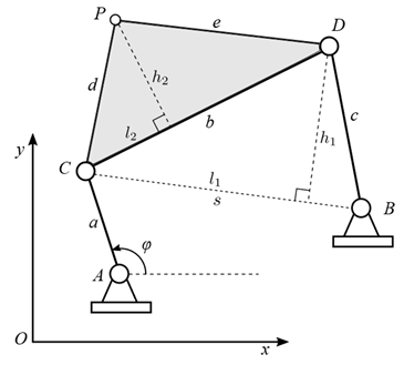
Figure 1: Four-bar mechanism modeling using natural coordinates
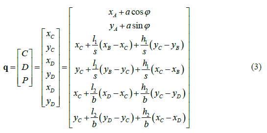
The figure illustrates the four-bar mechanism, where there is a defined natural coordinate vector q.
Since there is only one degree of freedom in this mechanism, the vector of degrees of freedom is written as ψ = [φ], which corresponds to an angular coordinate measured from the positive x axis. Six constraint equations are needed, which are described below.
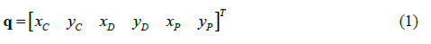
The objective is to find an alternative solution to the problem regarding the position of the four-bar mechanism, which is achieved by solving the equations mentioned above, whose problem is reduced by finding the cut-off points between two circumferences, as shown in Figure 2.
Figure 2: Open and cross-configuration of the four-bar mechanism
The resulting vector of natural coordinates is defined by q.
To determine the speeds and accelerations of the points of the aforementioned quadrilateral, a substitution of the variables mentioned by Nikravesh (2007) must be performed. To solve the system of equations, one must have knowledge of the speed of the degrees of freedom (initial velocity).
From the equation, it is concluded that
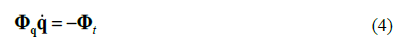
Where Φq is the Jacobian matrix of the restriction equations,
 is the vector of speeds to be found, and Φ
t
is the partial derivative of the constraint equations with respect to time.
is the vector of speeds to be found, and Φ
t
is the partial derivative of the constraint equations with respect to time.
Biomechanical study
Biomechanical analysis allows identifying and defining the variables involved in the gait cycle, such as the speed and acceleration of the different joints and the maximum and minimum angles during the flexion and extension phases. The use of specialized software such as KINOVEA allows observing processes that are imperceptible to the human eye, with which the behavior of the lower limb can be studied (Cáceres-Alvarado & Palacios-Mendoza, 2017). KINOVEA is a free-to-use video annotation tool designed for sport analysis. It features utilities to capture, slow down, compare, annotate, and measure motion in videos. Figure 3 shows the application of the software for the identification of the reference system used in the study of the patient's gait cycle.
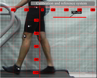
Figure 3: Reference system for the running cycle
A starting reference system was created by means of a platform and a grid sailcloth to measure body posture, with the purpose of obtaining more accurate data and establishing a speed of 1,8 km/h. A march study was then conducted on students of the University of Pamplona, during which the different phases of the march were observed as well as changes in the position, velocities, and accelerations of the knee joint through five cycles. The dynamic study of the lower limb began with the determination of the movement ranges of the knee joint, in order to obtain the maximum angles and critical points throughout the different phases (flexion and extension), in addition to the placement of markers at the points necessary for the analysis (greater trochanter, knee, and ankle joint), as shown in Figure 4.
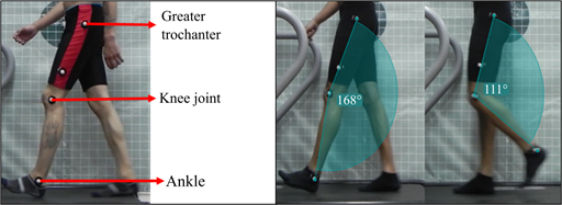
Figure 4: Anatomical points in the study of gait and knee extension and flexion angles
Variable identification
Once the markers were placed, the ankle and knee joints were followed in order to obtain the Cartesian coordinates of the ankle joint. Tracking points were used in the balancing phase with the joint as the reference center of the knee. Thanks to the graphic analysis of the videos of the ideal gait cycle, a real approximation of the desired curves was shown to the polycentric mechanism so it could replicate them. In Figure 5a, the ideal center of rotation of the knee is shown. This was done by means of a thorough analysis, in which specific points within the stability zone were defined. The knee changes its center of rotation when there is a variation in the angle of flexion. The points generated by the path made by the ankle joint in the oscillation phase were located, as shown in Figure 5b, thus obtaining the necessary Cartesian coordinates to generate the curves described by the joints. The coordinates in the x and y axes were determined for the previously located points, and, with some small variations in the data, the curves were made as smooth as possible.
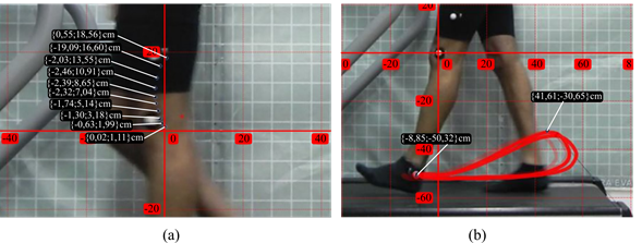
Figure 5: a) Knee CIR, b) ankle tracer
Using the experimental data from the points of interest in the lower limb, the trajectory of the studied point of the knee and the trajectory of the ankle in the swing phase of the gait were described, as shown in Figure 6a. After determining these curves, the optimization of the mechanism was carried out by means of a genetic algorithm, from which a mechanism that shows an approximation of the CIR was obtained from a biomechanical analysis, as shown in Figure 6b.
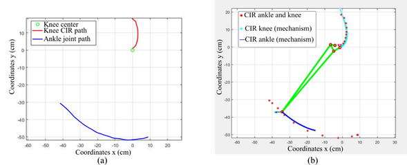
Figure 6: a) Curves described by the CIR of the knee and the ankle joint, b) optimal solution of the mechanism after the optimization process
The monitoring of the trajectories generated by the markers allowed identifying the velocity and acceleration of these points (markers) during the five gait cycles studied. The maximum velocity value (Figure 7a) occurs at the beginning of the balancing stage, that is, when the foot is at the midpoint of the oscillation movement. The negative acceleration values (Figure 7b) take place at the moment of contact between the foot and the surface, whereas the maximum values appear when the ankle is lifted from the ground, that is, when the walking cycle begins. In addition, in Figure 7, the time at which the joint is subjected to a constant load for a defined period of time (1 s) can be identified: while the lowest part of the limb (heel) is in contact with the ground.
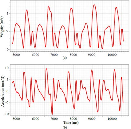
Figure 7: Data of the knee (markers) for five gait cycles: a) velocity and b) acceleration
RESULTS
The results of the optimization process allowed obtaining a mechanism with specific characteristics, for which the following link lengths were established: superior link (45,00 mm), inferior link (62,25 mm), curve link (37,50 mm), straight link (60,00 mm). The mechanism proposed for structural analysis follows the design guidelines presented by Castro-Valladares (2012). The CAD process was carried out with the help of the SOLIDWORKS 2018-2019 software while respecting the scaled measures. ANSYS was used for structural analysis, which works by modules depending on the system under study.
Engineering data
For the simulation of the polycentric knee mechanism, an aluminum alloy was used for the links and accessories, and 304L stainless steel was employed for the axles. The properties of each material are shown in detail in Table 1.
Source: Authors
Table 1: Material properties
Property
Aluminum alloy
Stainless steel 304L
Density (kg/m3)
2770
7850
Young module (GPa)
71
190
Poisson radius
0,330
0,265
Creep effort (MPa)
280
205
Tensile stress (MPa)
310
510
Model
In this stage, the mechanical interface of ANSYS R16 was employed. Initially, the materials were assigned: aluminum alloy and structural steel 304L. Subsequently, the type of contact was defined for each of the faces with node intersections. This was done to approximate the behavior of the assembly as close as possible to the real one. The mesh determination was the result of the metric convergence between the elements. The optimal element size obtained from the simulation was 2 mm, given that, with this configuration, there is a greater number of nodes and elements and the characteristics of the mesh are better than in configurations with a larger average element size.
The next step was meshing the model. A mesh with a form function was configured in order to use the mechanical-physical preference type, the Mechanical APDL solver in iterative mode to find the solution, and tetrahedral elements with an average size of 2 mm, which was obtained from the mesh study shown in Figure 8. The mesh converges to the solution in such a way that the computational time is optimized. The meshing of the piece has defined characteristics to improve the quality of the results, such as a fine relevance center, high smoothing, slow transition, and a fine expansion angle center.
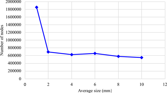
Figure 8: Mesh convergence
Load configuration
The piece was subjected to a standard gravity of 9,807 m/s2. Moreover, in the upper part, a uniformly distributed load of 2.000 N was placed on the upper face, and a position restriction was imposed on the mechanism, which did not allow movement in the other directions.
Solution
For the model analysis, the following relevant solutions were applied:
-
Total deformation
-
Equivalent effort (Von Mises)
-
Security factor
-
Fatigue factor
The load was parameterized in order to obtain several design points and characterize the behavior of the polycentric knee mechanism. To determine the fatigue behavior the load, the amplitude rate was used, applying the load for a period of 1 s. Additionally, Goodman's theory of failure was defined according to studies conducted in this type of geometry (Amador et al., 2012).
Parameterization
The results of the parameterization of the load are shown in Table 2. The data show an increase in the values of maximum deformation and equivalent stress, as well as a decrease in the safety and fatigue factors, as the applied load increased.
Source: Authors
Table 2: Parameterization of the applied loads
Design point
Nodal force (N)
Maximum total deformation (mm)
Maximum equivalent effort (MPa)
Security factor
Fatigue factor
1
500
0,033979
8,6937
>15
>15
2
1000
0,068031
17,381
>15
7,5152
3
2000
0,135390
38,873
7,8052
3,6411
The results obtained at design point number 3 demonstrate an ability to withstand loads above 2.000 N. Additionally, the structure has a total mass of 1,018 kg.
Total deformation
This section presents the results of the simulation with respect to the total deformation produced in the prosthesis from a point load applied on its upper surface, which simulated two times the weight exerted by an average person. Figure 9a shows the maximum value of the deformation obtained in the simulation (0,13639 mm). The observed deformation under maximum load can lead to conclude that the elements are designed to work in the plastic zone of the materials, within which no significant total deformation is evidenced.
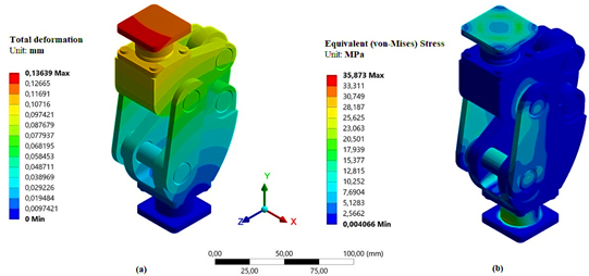
Figura 9: Model simulation results: a) total deformation and b) equivalent effort (Von Mises)
Equivalent effort (Von Mises)
As can be concluded from the results obtained, this element is not damaged by applying a static point load on its upper surface, which simulates a mass greater than 200 kg.
It is of great importance to highlight that the highest values are found in the upper and lower supports, where elements with right angles are evidenced and the change in the cross-section is abrupt. Another important parameter provided by this application is the security factor. These values contribute to reducing the failure of the material due to overload. A static load security factor and a dynamic fatigue load factor corresponding to 7,8052 and 3,6411, respectively, were obtained from the simulation. The maximum effort was approximately 35 MPa and located on the upper surface (Figure 9b).
CONCLUSIONS
By studying the background of this type of work, it can be concluded that there is no established method for determination and optimization that converges to the location of the center of rotation of the knee. The use of natural coordinates should be considered as an efficient and concise method because it implies simpler equations and therefore involves the use of a smaller number of angular coordinates. According to the results obtained through the optimization process, an efficient method for determining the lengths of the links was obtained since the CIR of the mechanism closely resembled the CIR described by the knee joint, which was defined by the biomechanical analysis of the videos. The curves generated after the optimization process closely resemble those observed in the biomechanical analysis, which indicates that this method can be used in other studies that require the use of polycentric mechanisms, since they generate defined trajectories. According to the results obtained in the simulation, it was evidenced that the prosthesis model is structurally functional under static and dynamic loads that exceed nominal real load values.
Acknowledgements
ACKNOWLEDGMENTS
The authors gratefully acknowledge the financial support provided by the Mechanical Engineering program of Universidad de Pamplona, as well as the technical support provided by the Biomechanics Laboratory of the Department of Physical Education.
REFERENCES
Licencia
Esta licencia permite a otros remezclar, adaptar y desarrollar su trabajo incluso con fines comerciales, siempre que le den crédito y concedan licencias para sus nuevas creaciones bajo los mismos términos. Esta licencia a menudo se compara con las licencias de software libre y de código abierto “copyleft”. Todos los trabajos nuevos basados en el tuyo tendrán la misma licencia, por lo que cualquier derivado también permitirá el uso comercial. Esta es la licencia utilizada por Wikipedia y se recomienda para materiales que se beneficiarían al incorporar contenido de Wikipedia y proyectos con licencias similares.