DOI:
https://doi.org/10.14483/22487638.16533Publicado:
01-04-2020Número:
Vol. 24 Núm. 64 (2020): Abril - JunioSección:
InvestigaciónPermittivity experimental determination as a frequency function
Determinación experimental de la permitividad como función de la frecuencia
Palabras clave:
Capacitors, complex capacitance, complex permittivity, frequency circuits (en).Palabras clave:
condensadores, capacitancia compleja, permitividad compleja, circuitos de frecuencia. (es).Descargas
Referencias
Ardila, A. M. (2007). Física Experimental - Colección notas de clase (1st ed.). Bogotá Colombia: Universidad Nacional de Colombia.
Belden, I. (2018). Datasheet Belden Wire RG-8.
Biolock Scientific, F. (2000). Stereo Microscopes Stemi 1000/2000/2000-C. Field guide to microscopy. https://doi.org/10.1117/3.798239.ch43
Blaž, N., Radosavljević, G., Živanov, L., & Smetana, W. (2009). Characterisation of dielectric LTCC tapes using the capacitance method. Proceedings of the International Semiconductor Conference, CAS, 2(2), 447–450. https://doi.org/10.1109/SMICND.2009.5336682
Casas Piedrafita, O., & Rossel Ferrer, J. (1998). Contribución a la obtención de imágenes paramétricas en tomografía de impedancia eléctrica para la caracterización de tejidos biológicos.
Coffey, W. ., & Kalmykov, Y. . (2006). Fractals , Diffusion and Relaxation in Disordered Complex Systems : Advances in Chemical Physics. https://doi.org/10.1002/0470037148
Deabes, W. A., Abdelrahman, M. A., & Murray, C. (2008). Analysis, design and application of a capacitance measurement circuit with wide operating frequency range. Proceedings of the IEEE International Conference on Control Applications, 114–120. https://doi.org/10.1109/CCA.2008.4629613
Duane A. Felton. (1965). Propiedades dielectricas cerámicas. State University of New York College of Ceramics Aldred University.
Electronics, I. inc. (n.d.). HIGH VOLTAGE CERAMIC CAPACITOS.
Frubing, D. P. (2001). Dielectric spectroscopy, (0331), 1–21.
González, A. F. (2009). Capacitores.
Hernández Millán, G., Ríos Gonzales, L. H., & Bueno López, M. (2016). Implementación de un controlador de posición y movimiento de un robot móvil diferencial. Tecnura, 20(48), 123-136. https://doi.org/10.14483/udistrital.jour.tecnura.2016.2.a09
Israelsohn, J. (2008). Know your ceramic capacitor, part two, 2.
Jee, W., Raymond, K., Kumar, C., Chin, G., & Basri, A. (2013). Complex permittivity measurement using capacitance method from 300 kHz to 50 MHz. Measurement, 46(10), 3796–3801. https://doi.org/10.1016/j.measurement.2013.06.039
Marulanda Durango, J. J., Escobar Mejía, A., & Alzate Gómez, L. A. (2017). Estudio comparativo de cinco estrategias de compensación de armónicos en filtros activos de potencia. Tecnura, 21(52), 15-31. https://doi.org/10.14483/udistrital.jour.tecnura.2017.2.a01
Massy, P. (2005). Dielectric characteristics of glass fi bre reinforced plastics and their components, 32(11), 20–22.
Maxim Integrated Products. (2001). Current-Feedback Amplifiers with Shutdown o Low Distortion : TOP SINGLE FOR Current-Feedback Amplifiers with Shutdown.
Motic, M. T. M. (2003). BA300Pol. Polarizing Microscope. International.
Murata Manufacturing. (2006). Capacitance and Dissipation Factor Measurement of Chip Multilayer Ceramic Capacitors, 19. Retrieved from http://www.murata.com/~/media/webrenewal/support/faqs/products/capacitor/mlcc/char/0007/07_capmeasureen.ashx?la=en
Neri Vela, R. (1999). Lineas de Transmisión. Mexico.
Newfoundland, U. of. (2010). Logarithmic Graphs.
Otto, S., Bettray, A., & Solbach, K. (2009). A Distributed Attenuator for K-Band using Standard SMD Thin-Film Chip Resistors, 2148–2151. https://doi.org/10.1109/APMC.2009.5385509
Patri, S. K. (2016). Dieleectric Materials: Introduction, Research and Applications, (January 2009).
Schulz, A. L. (2011). CAPACITORS: THEORY, TYPES AND APPLICATIONS. New York: Nova Science Publishers, Inc.
Sevila, D. E.-E.-U. de. (2001). Laboratorio de Síntesis de Circuitos- Ingeniería de Telecomunicación- Tercer curso SPICE.
Spacing, A. L. (1988). Disc Ceramic Capacitors General Specifications - Class II General Purpose General Specifications - Class II General Purpose.
Strååt, M., Chmutin, I., & Boldizar, A. (2010). Dielectric Properties of Polyethylene Foams at Medium and High Frequencies, 18(1).
Stuerga, D. (2006). Microwave – Material Interactions and Dielectric Properties , Key Ingredients for Mastery of Chemical Microwave Processes.
TDK (Mouser electronics). (2016). Disk Type Capacitors with Lead CC45 series.
Tektronix. (n.d.). AFG3000 Series Arbitrary / Function Generators Manual. Retrieved from www.tektronix.com
Vega Pérez, C. J., & Alzate Castaño, R. (2015). Control óptimo inverso como alternativa para la regulación de un convertidor DC-DC elevador. Tecnura, 19(46), 65-78. https://doi.org/10.14483/udistrital.jour.tecnura.2015.4.a05
Cómo citar
APA
ACM
ACS
ABNT
Chicago
Harvard
IEEE
MLA
Turabian
Vancouver
Descargar cita
Recibido: 20 de septiembre de 2019; Aceptado: 5 de febrero de 2020
ABSTRACT
Objective:
To determine the behavior of dielectric permittivity of class II ceramic capacitor in function of frequency up to 10MHz.
Context:
in telecommunications and high frequency circuits is necessary to take into account the diminishing of permittivity on dielectrics of ceramic capacitors with the frequency growth, two quantitative methods are proposed to determine this behavior.
Method:
First, the impedance meter bridge FLUKE PM5306 was used in the frequency range from 10^2 Hz to 10^5 Hz; and second, a novel low-cost electronic circuit for the frequency range between 10A4 Hz to 10A7.
Results:
The results from the circuit were validated using the impedance meter bridge RLC FLUKE PM 6306. The measure of the complex capacitance from three capacitors and their loss tangent were obtained.
Conclusions:
The capacitance decreasing with the increment of the frequency was observed in the impedance meter bridge and the implemented circuit, finding a convergence between both methods in the common frequency region.
Keywords:
Capacitors, complex capacitance, complex permittivity, frequency circuits.RESUMEN
Contexto:
En telecomunicaciones y los circuitos en alta frecuencia es necesario tener en cuenta la disminución de la permitividad de los dieléctricos en capacitores cerámicos con el aumento de la frecuencia, se proponen 2 métodos cuantitativos para determinar el comportamiento.
Método:
Primero se utilizó el puente medidor de impedancias FLUKE PM6306 en el rango de frecuencias entre 10^2 Hz hasta 10^5 Hz, y segundo, un circuito electrónico novedoso de bajo costo para frecuencias entre 10A4 Hz hasta 10A7 Hz.
Resultados:
Se validaron los resultados obtenidos con el circuito contrastándolo con el puente de impedancias RLC FLUKE PM6306. Se obtuvo la medición de la capacitancia compleja de tres diferentes condensadores, así como la tangente de pérdidas asociada.
Conclusiones:
Se observó la disminución de la capacitancia con el aumento de la frecuencia a través del puente de impedancias, así como con el circuito implementado, encontrando convergencia entre los dos métodos en la región común de frecuencia.
Palabras clave:
condensadores, capacitancia compleja, permitividad compleja, circuitos de frecuencia.INTRODUCTION
The dielectric permittivity is the measure of the response of an electrical insulator in presence of an external electric field. The electric charge in atoms and molecules of non-conducting materials deforms and tries to turn the molecules following the direction of the electric field (i.e. the polarization phenomenon). A high value of permittivity indicates a high polarization with changes in physical properties of this materials in response to an external electric field that varies in time (Duane A. Felton, 1965).
The behavior of permittivity as a frequency function, affects the performance of the circuit elements that include dielectrics. In particular, the capacitors have non-conducting materials in order to improve the charge storing, bringing mechanical support and isolating between the conducting plates (González, 2009). These elements must be studied with the purpose of determining its stability and functionality as a frequency function in alternating current circuits. Some of its applications include: charge source or storage to be quickly freed, frequency filters, electronic memories, oscillators, tension multipliers, derivative and integral circuits, etc. (Schulz, 2011). The behavior of dielectric in frequency circuits is represented by a complex permittivity because the material's polarization has a response time when an electric field with time dependency is applied. In order to know the behavior of the permittivity, the physical model of complex capacitance allows to measure its admittance (complex impedance) making it possible to relate these magnitudes and the permittivity (Casas Piedrafita & Rossel Ferrer, 1998). Therefore, this research is focused on commercial capacitors used in electronics, telecommunications, electrical engineering, and other disciplines that use capacitors in high frequency circuits up to 10Mhz. We present two methods of measurement according to the frequency range: a capacitor bridge (102-105 Hz), and a capacitance measurement circuit (104-107 Hz), which is an innovative and low cost circuit useful as instrumentation circuit of capacitive sensors in AC current circuits.
PHYSICAL FOUNDATIONS
At the beginning of the 20th century, Peter Debye developed the theory of dynamical response of permittivity as a frequency function with a base of experiments in dipole liquids (Patri, 2016). The polarization behavior is determined regarding the frequency of the external field; thus, the permittivity is represented by a complex number. In order to study the energy losses in the material (Stuerga, 2006), Debye defines the relative permittivity in the complex form:
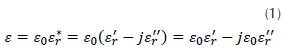
Where εr is the relative permittivity, ε'r is the real component of the permittivity, ε"r the imaginary part and ε0 the free space permittivity. It is possible to define a complex capacitance (Coffey & Kalmykov, 2006) from equation (1), and for the parallel plate condenser capacitance C=εA/d, thus

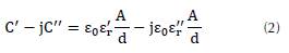
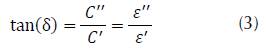
From Equation (2) the complex permittivity (real and imaginary components) can be determined from capacitance measurements. It is possible to represent the energy losses not included in ideal representation by defining the losses tangent of dissipative factor δ (Frubing, 2001):
The standard IEC/EN 60384 classifies the non-polar SMD (Surface Mount Device) capacitors in three different classes by their behavior considering frequency and temperatures. (KEMET, 2015, 2018a, 2018b) presents the relevant data of every class. Class I dielectrics are the ones with the best performance in frequency, so this is the one used as reference, while most of the low cost through hole capacitors used in electronic applications are Class II, thus its frequency behavior must be taken into account.
The following section presents the experimental methods used in this work to measure the permittivity.
METHOD
It is possible to obtain the capacitance as a frequency function by using measurement bridges. In this case, the FLUKE-PM6306 is capable to determine the frequency function of a condenser following the real capacitance model, and the capacitor does not respond like an open circuit because the capacitor has a resistive and inductive behavior. This device is useful to work in the range of 50Hz to 1Mhz. Likewise, a logarithmic sample of data is used to make an equitable distribution of every decade (Newfoundland, 2010).
With the purpose of extending the frequency range in this work, it is necessary to implement an electronic circuit of low cost and excellent response in higher frequencies. This circuit was developed using the work of (Deabes, Abdelrahman, & Murray, 2008) with improvements and innovations. The implemented circuit, which is composed from an active filter (Marulanda et al, 2017), has the advantage that it does not require changes in the circuit's elements, by means of the fast speed operational amplifier MAX4182, used in cameras and Radio Frequency receptors (Maxim Integrated Products, 2001). The new design includes the adaptation of different circuit elements, such as the implementation of bypass capacitors, SMD resistances, and the use of class I capacitors as reference. Furthermore, the tested capacitor from a local commerce was manufactured for different engineering applications, with the glass fiber as the circuit base, its low dielectric permittivity (Massy, 2005), and the use of different values of impedance, which were calculated to improve the frequency response of the circuit.
Moreover, it is necessary to use electric probes in order to develop the measurement process using signal generation, connection with oscilloscope, and data acquisition. Given its capacitive behavior in AC signals, these electric probes were constructed to diminish the losses by impedance and attenuation (Neri Vela, 1999). The coaxial cable with a characteristic impedance of 50 H was used to guarantee a good coupling between the signal generator, the input of the capacitance measurement circuit, and the oscilloscope (Neri Vela, 1999). By fulfilling two criteria, the RG8/U coaxial cable was chosen according with its datasheet information (Belden, 2018), with losses of 1.7 dB every 100 ft at 100 MHz. The dielectric inside the coaxial cable is foamed polyethylene, which has a permittivity in a range of 1.3 to 3 following its porosity at low frequency (Straat, Chmutin, & Boldizar, 2010). Based on the permittivity of dielectric inside the coaxial, the maximum wavelength in the propagation media at the high frequency is calculated (Neri Vela, 1999)
 . Two coaxial probes were constructed (whose lengths are 15cm and 17cm, respectively); these probes are not going to present reflected waves because the sizes are less than the maximum length wave.
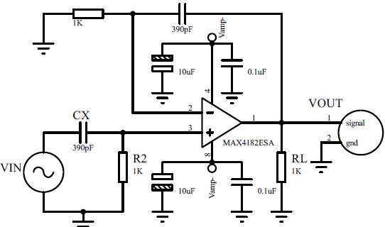
Figure 1: Experimental design of the final circuit used to make the measurements.
The signal generator used was the TEKTRONIX AFG3102 with an uncertainty in sinusoidal signal in frequencies under 5Mhz of ±0.15 dB; however, for frequencies between 5Mhz and 25Mhz uncertainty is ±0.3dB (Tektronix, n.d.). The oscilloscope used was the TEKTRONIX DPO7054C, which is capable of eliminating external noise by adjusting the bandwidth with internal signal processing; the bandwidth was adjusted to 20Mhz, with losses around the top frequency (i.e. 10 MHz, see Bode diagram). Adding losses in the signal generator and the behavior of coaxial probes made it possible for a real compensation of the circuit to guarantee a better calculation of the input voltage for the experimental model.
Without correction, the AC entry signal changes its amplitude from 0.98V to 1.03V, while the compensated signal change stays the range 0.99V to 1.01V (Vega, Alzate, 2015). Regarding the resistances, the SMD technology was used due to its accurate response up to 10Ghz (Otto, Bettray, & Solbach, 2009). Three through-hole ceramic capacitors with a nominal value of 390pF were chosen for the test. These capacitors have parallel plate geometry with different dielectric characteristics (permittivity, disruption value, etc.) (Electronics, n.d.;Spacing, 1988; TDK (Mouser electronics), (2016). Likewise, the capacitors C- y C+ (Figure 1). were used as bypass capacitors (Maxim Integrated Products, 2001).
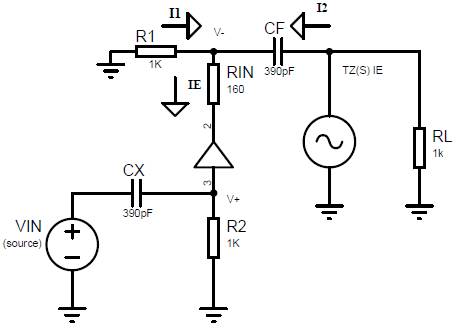
Figure 2: Real model of operational amplifier MAX4182.
Two functions were used in order to understand the behavior of the circuit. First, the Laplace Transform to simulate the frequency behavior of the circuit and the values of circuit elements, which guarantee the experimental bandwidth. Second, the complex capacitance Cx was found using the Fourier Transform.
Using Kirchhoff laws, the tension in V+node is found to be
 . In V-node the current is ie=i1+i2, then by compar ison
 and
and

By replacing:
Now,
 which is the function that describes the behavior of MAX4182 as frequency response, the magnitude of transimpedance of the operational amplifier, T
z
=3×10⁶Ω and
which is the function that describes the behavior of MAX4182 as frequency response, the magnitude of transimpedance of the operational amplifier, T
z
=3×10⁶Ω and
 is the cut angular frequency. To have a gain of one, the value R
in
=160Ω (Maxim Integrated Products, 2001), thus:
is the cut angular frequency. To have a gain of one, the value R
in
=160Ω (Maxim Integrated Products, 2001), thus:
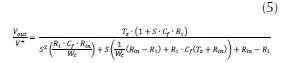
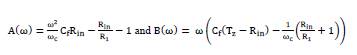
Finally, the transfer function of the circuit is:
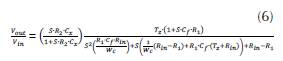
In contrast, (Deabes et al., 2008) only indicates the resulting transfer function with algebraic mistakes, and therefore our transfer function differs from the presented function in that work. To find the capacitance C
x
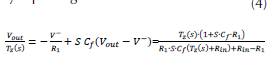
, it is necessary to use the Fourier Transform, given that Cf is a capacitor class I that can be taken like ideal. First, the tension of V+ is
 and by replacing the currents and using variable separation:
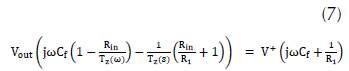
 which is the behavior of the circuit in terms of Fourier transform and:
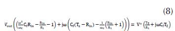
Calling two auxiliary functions:
Finally, by algebraic development C x :
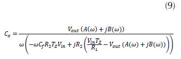
C
x
is the complex capacitance that let us determine the complex permittivity of the material under test. Beginning with the Z
Th
the Thevening impedance venin in VIN entrance to obtain the impedance value for the coupling of a signal generator
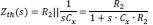 where s=2πf, by taking the frequency cuts 10Khz and 10Mhz, with R
2
=103Ω and C
x
=390∙10
−12
f, it is calculated Z
th
(s=2π∙10
4
Hz)=976,082Ω and Z
th
(s=2π∙10
7
Hz)=39,21Ω.
where s=2πf, by taking the frequency cuts 10Khz and 10Mhz, with R
2
=103Ω and C
x
=390∙10
−12
f, it is calculated Z
th
(s=2π∙10
4
Hz)=976,082Ω and Z
th
(s=2π∙10
7
Hz)=39,21Ω.
The operational MAX4182 is optimized to handle little capacitances and impedances of the Z th order.
The Datasheet recommends a resistance load RL of 10 3 Ω; so, for the resistances R and R 2 we chose a similar resistance with a value of 10 3 Ω to assure a coupling between generator-circuit-oscilloscope, with the capacitance range for the circuit goes to 1nF . The model of circuit has significant characteristics in high frequency.
To determine its correct function, the OrCAD LTI Spice Lite (Sevila, 2001) software was used, which takes into account the real behavior of MAX4182 operation amplifier. By this simulation it is possible to have a logarithmic sweep in frequency to elaborate a Bode diagram in the Figure 3.
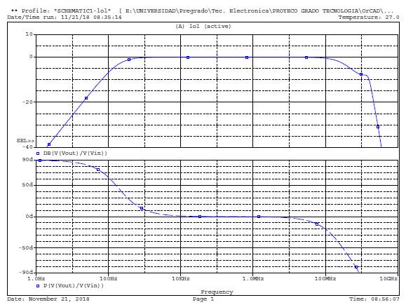
Figure 3: Bode diagram model circuit in OrCAD.
The Bode diagram shows the working range of 10Khz to 10Mhz, region of dipolar polarization phenomena (Patri, 2016). Automatic data acquisition from the circuit was made with the use of instrument Control Toolbox found in MATLAB. (Hernández, Gonzales, & Bueno, 2016).
To obtain the complex permittivity, it is necessary to know the geometrical dimensions of the dielectric inside the capacitor tested. The first instrument used for this work is the microscope MOTIC BA 300pol (Motic, 2003), and the second is the Stereo Microscope ZEIZZ STEMI 2000-C (Biolock Scientific, 2000) to measure the 5kV (Electronics, n.d.) by size. The measurement process starts by taking a digital image on the lens' focus which is analyzed with Adobe Reader software. With the real dimension of focus distance and locating the capacitor's center in the axis of the lens, there is a direct relationship between the pixel number and the longitude. The measurements are shown in Table 1.
Source: Authors.
Table 1:: Geometrical dimensions of dielectrics from capacitors class ll.
Element
Diameter
Width (mm)
(mm)
Capacitor 50V
3,52 ± 0,005
0,79± 0,005
Capacitor 2kV
4,48± 0,005
0,73± 0,005
Capacitor 5kV
6,4± 0,05
1,55± 0,005
RESULTS
In this section the capacitance curves as frequency function obtained by RLC FLUKE PM6306 bridge and the implemented circuit are analyzed. Besides, in the case of the proposed circuit the complex parts were calculated. Finally, the tangent of losses graphics is shown to determine the quality of capacitors under test. Every measurement has its propagated uncertainty value represented by vertical error bars. The uncertainty of the FLUKE PM6306 was given by its datasheet (FLUKE. (n.d.)), with the uncertainty of the capacitance present in the corresponding frequency stop with N=20, for the standard deviation corrected using a T-student test (Ardila, 2007). The data from the Bridge up 100KHz were used to compare the first measured decade of the implemented circuit with the final data of PM6306 bridge. Figure 4. shows the diminishing of capacitance as a function of frequency, in accordance with EIA 198 standard (Israelsohn, 2008). The 2kV capacitor shows mayor capacitance decreasing.
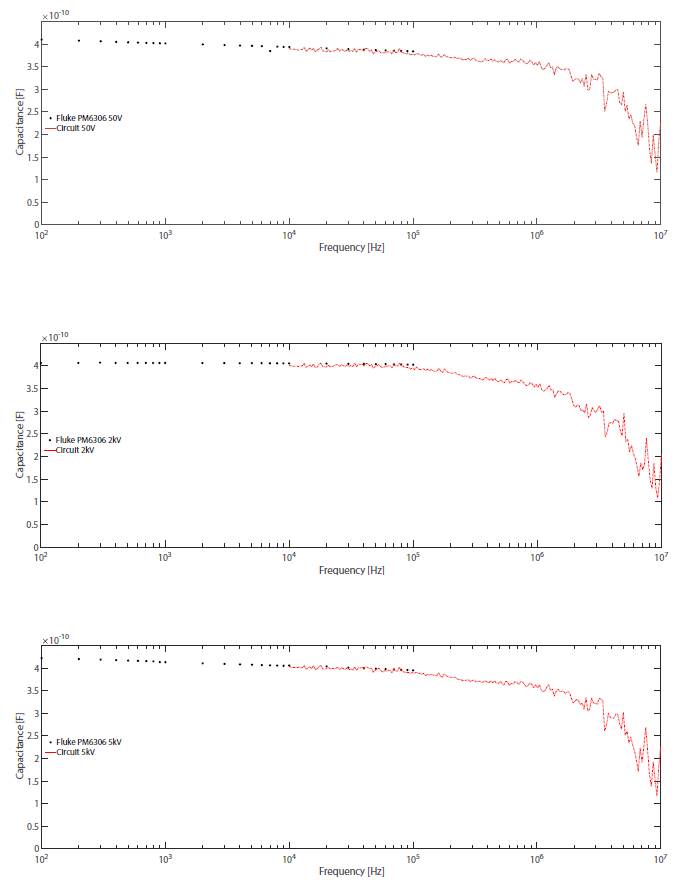
Figure 4: Capacitances as frequency function by FLUKE PM6306 Bridge and proposed electronic circuit.
The previous data were used to compare the first measured decade of the implemented circuit with the final data of PM6306 bridge. Figure 5. shows the diminishing of capacitance as a function of frequency, in accordance with EIA 198 standard (Israelsohn, 2008). The 2kV capacitor shows mayor capacitance decreasing. From the concept of tangent losses, it is possible to determine the quality of the capacitors: a better capacitor must evidence lower losses. In Figure 6. the comparison of the three capacitors is shown.
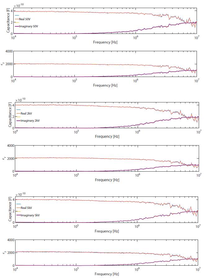
Figure 5: Ceramic capacitor class ll. Capacitance and permittivity (Real and Imaginary components).
According to the literature (Murata Manufacturing, 2006), the variation of tangent losses of dielectrics used in class II capacitors is found in the range of 0.05 to 0.15 in a frequency range between 30kHz to 500kHz, which agrees with our test. From frequencies of 1MHz there is an evident grow in tangent losses in the three cases, which is inversely related to the quality factor Q (Frubing, 2001) and shows that class II capacitors can be used up 1MHz and perform well.
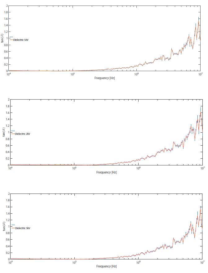
Figure 6: Losses Tangent as a frequency function for three capacitors under test. In order: 50V Capacitor, 2kV Capacitor and 5kV Capacitor.
CONCLUSIONS
The FLUKE PM6306 bridge measures the capacitance at low frequencies and complements the data obtained in the implemented circuit, thus achieving a frequency sweep from 100 Hz to 10 MHz that allows seeing the polarization of space and dipolar charges in dielectrics, highlighting the data in the shared frequencies of both methods.
Through the Bode diagram calculated from the transfer function, it is verified that the implemented circuit is stable in the frequency range from 10kHz to 10Mhz. When performing a compensation that guarantees a negligible variation in the amplitude of the input signal, the circuit satisfies the measurement of the complex capacitance and the complex permittivity for a capacitor with low capacitance. In this way, the only parameter expected to change as a function of frequency is the unknown capacitance.
The price of the implemented circuit was 24.8 USD, which is low when compared to the price of the FLUKE bridge PM6306 (around of 2150 USD). Hence, its implementation is recommended for capacitance and dielectric permittivity measurements in a stable frequency range.
The behavior of the real part of the dielectric of class II ceramic capacitors decreases from 3500 to 1000 in the 50V capacitor, from 2100 to 600 in the 2kV capacitor, and from 2100 to 500 in the 5kV capacitor. This occurs due to polarization changes in the dipolar region produced by the electric field applied. At the same time, it increases in the imaginary part, highlighting that the 50V capacitor increases to approximately 2800, the 2kV capacitor to 900, and the 5kV capacitor to 1000 capacitor. This phenomenon physically demonstrates the decrease in dielectric permittivity.
The losses tangent allowed the comparison between the three measured dielectrics, concluding that the dielectric permittivity of the ceramic capacitor of 5KV is the one with the best behavior since at 10 MHz it had a peak of 1.8, while the capacitors of 50 V and 2KV had peaks of 2. The tested Class II ceramic capacitors do not behave properly at frequencies above 1MHz due to the increase in the losses tangent, causing the decrease of the quality factor in the measured elements. Thus, the use of these capacitors in resonant circuits with a higher frequency than this is not recommended.
Acknowledgements
ACKNOWLEDGEMENTS
First, to God for allowing us to make this scientific contribution to technological knowledge. To the group GICE of the University Francisco José de Caldas, and its director Dr. Danilo Rairán for the opportunity to develop this work in the group's laboratory facilities. Also, to the High Voltage and Thermoelectric Laboratory, and to the Maderas Laboratory, at the University Francisco José de Caldas. We also thank the Department of Geosciences, at the National University of Colombia. To all who gave us their support in all the questions generated during the development of this project.
REFERENCES
Licencia
Esta licencia permite a otros remezclar, adaptar y desarrollar su trabajo incluso con fines comerciales, siempre que le den crédito y concedan licencias para sus nuevas creaciones bajo los mismos términos. Esta licencia a menudo se compara con las licencias de software libre y de código abierto “copyleft”. Todos los trabajos nuevos basados en el tuyo tendrán la misma licencia, por lo que cualquier derivado también permitirá el uso comercial. Esta es la licencia utilizada por Wikipedia y se recomienda para materiales que se beneficiarían al incorporar contenido de Wikipedia y proyectos con licencias similares.