DOI:
https://doi.org/10.14483/23448393.22111Published:
2025-08-01Issue:
Vol. 30 No. 2 (2025): May-AugustSection:
Electrical, Electronic and Telecommunications EngineeringMethodology Based on the Squared Error Integral for the Design of Fuzzy Controllers
Metodología basada en la integral del error al cuadrado para el diseño de controladores difusos
Keywords:
Fuzzy controller design, Fuzzy experimental method, riterion of squared error integral, Mamdani controller, membership function parameterization (en).Keywords:
Diseño de controladores difusos, método de diseño fuzzy, criterio de la integral del error al cuadrado, controlador Mamdani, parametrización de la función de membresía (es).Downloads
References
I. Mazon and J. Ramírez, “Ajuste de controladores difusos mediante algoritmos genéticos,” Ing, Revista de la Universidad de Costa Rica, vol. 9, no. 1–2, pp. 95–107, Sep. 2011. https://doi.org/10.15517/ring.v9i1-2.7726
E. R. Moo-Medina and D. Romero, “Speed control of a DC motor with a type-2 fuzzy logic controller subject to a large disturbance,” Comp. Sist., vol. 22, no. 2, pp. 521–536, Jul. 2018. https://doi.org/10.13053/cys-22-2-2251
J. Calderón, I. V. Parra, and H. Montana, “Controladores difusos en microcontroladores: software para diseño e implementación,” Vis Elect, vol. 4, no. 2, pp. 64–76, 2010. https://doi.org/10.14483/22484728.273
M. L. Rodríguez and Y. E. Huertas, “metodología para el diseño de Conjuntos Difusos Tipo-2 a partir de Opiniones de Expertos,” Ing., vol. 21, no. 2, pp. 121–137, May 2016. https://doi.org/10.14483/udistrital.jour.reving.2016.2.a01
H. A. Yousef, “Fuzzy logic control of DC motor drives,” IFAC Proc., vol. 30, no. 6, pp. 751–756, May 1997. https://doi.org/10.1016/s1474-6670(17)43455-0
D.-I. Kim, J.W. Lee, and S. Kim, “Fuzzy algorithm for commutation of permanent magnet AC servo motors without absolute rotor position sensors,” in Proc. 1992 Int. Conf. Ind. Elect. Control Instrum. Automat. IEEE, pp. 144–149. https://doi.org/10.1109/iecon.1992.254590
Y.-S. Kung and C.-M. Liaw, “A fuzzy controller improving a linear model following controller for motor drives,” IEEE Trans. Fuzzy Syst., vol. 2, no. 3, pp. 194–202, 1994. https://doi.org/10.1109/91.298448
A. J. Agama, C. Cevallos, R. V. García, andW. Maliza, “implementación de control de velocidad de un motor dc con controlador pid convencional y difuso p-pi-pid con diferentes tipos de entradas utilizando software Labview,” J Sci. Res., vol. 5, no. 2, pp. 227–243, 2020.
L. Fitz, J. R. García, J. Rodríguez, and R. V. Carrillo, “diseño de un controlador de velocidad con base en lógica difusa para un motor de CD,” in Cong. Int. Invest. Acad J. Celaya 2021, vol. 13, no. 10, 2021, pp. 848–853.
F. Betin, D. Pinchon, and G.-A. Capolino, “Fuzzy logic applied to speed control of a stepping motor drive,” IEEE Trans. Ind. Elect., vol. 47, no. 3, pp. 610–622, Jun. 2000. https://doi.org/10.1109/41.847902
M. Masiala, B. Vafakhah, J. Salmon, and A. M. Knight, “Fuzzy self-tuning speed control of an indirect field-oriented control induction motor drive,” IEEE Trans. Ind. Appl., vol. 44, no. 6, pp. 1732–1740, 2008. https://doi.org/10.1109/TIA.2008.2006342
P. Parikh, S. Sheth, R. Vasani, and J. K. Gohil, “Implementing fuzzy logic controller and PID controller to a DC encoder motor: A case of an automated guided vehicle”,” Proc. Manuf., vol. 20, no. 2, pp. 219–226, 2018. https://doi.org/10.1016/j.promfg.2018.02.032
H. Maghfiroh, J. Slamet Saputro, F. Fahmizal, and M. Ahmad Baballe, “Adaptive fuzzy-PI for induction motor speed control,” J. Fuzzy Syst. Control., vol. 1, no. 1, pp. 1–5, Mar. 2023. https://doi.org/10.59247/jfsc.v1i1.24
M. Almaged, A. Mahmood, and Y. H. S. Alnema, “Design of an integral fuzzy logic controller for a variable-speed wind turbine model,” J. Robot Control, vol. 4, no. 6, pp. 762–768, Nov. 2023. https://doi.org/10.18196/jrc.v4i6.20194
J. C. Munoz-Esparza and J. E. Jaime-Leal, “A novel approach to a recurrent fuzzy logic controller design applied to systems with multiple disturbances,” J. Chem. Eng. Theor. Appl. Chem., vol. 81, no. 602, May 2024. https://doi.org/10.55815/428834
R. K. Signe and F. B. Motto, “Fuzzy-PID controller based sliding-mode for suppressing low frequency oscillations of the synchronous generator,” Heliyon, vol. 10, no. 15, p. e35035, Aug. 2024. https://doi.org/10.1016/j.heliyon.2024.e35035
K. Ogata, Ingenieria de control moderna, 5th ed. Madrid, Espana: Pearson, 2010.
K. M. Passino and S. Yurkovich, Fuzzy control, 1st ed. Menlo Park, Calif.: Addison-Wesley, 1998.
N. Shahbazova, S. Michio, and K. Janusz, “Recent developments in fuzzy logic and fuzzy sets,” Stud. Fuzziness Soft. Comput., vol. 1, no. 1, p. 211, Mar. 2020. https://doi.org/10.1007/978-3-030-38893-5
K. Ogata, Discrete-time control syst, 2nd ed. Upper Saddle River, N.J.: Prentice-Hall, 1998.
M. Kai, K. Frank, K. Rudolf, and N. Andreas, “Fuzzy control: fundamentals, stability and design of fuzzy controllers,” Stud. Fuzziness Soft Comput., vol. 1, no. 1, p. 402, May 2006. https://doi.org/10.1007/3-540-31766-X
How to Cite
APA
ACM
ACS
ABNT
Chicago
Harvard
IEEE
MLA
Turabian
Vancouver
Download Citation
Recibido: 30 de abril de 2024; Aceptado: 23 de julio de 2025
Abstract
Context:
This work applies an experimental methodology to the design of a control system based on a non-conventional Mamdani fuzzy controller that regulates the speed of an encoder-based DC motor.
Method:
The proposed methodology consists of four steps: i) fuzzy controller input/output selection, ii) fuzzy controller design, iii) controller hardware implementation, and iv) membership function parameterization. This methodology generates seven pairs of unique error and control signals that are differentiated by experimentally adjusting the parameters of the triangular membership functions used for the fuzzy controller design, which was implemented in an Atmega328P micro-controller. For each of the seven approaches defined, an experiment was performed, performing a control action to obtain the transient response of the DC motor speed when the reference was a step-type signal.
Results:
The motor response and the reference signal were used to calculate the error, whose squared error integral was estimated to determine which experimental approach yielded the best fuzzy control results, i.e., with the lowest possible error.
Conclusions:
The proposed methodology ensures the minimization of the squared error integral between the signal to be controlled and the reference signal. For fitting 6, the performance index obtained was J = 0.0002, which represents a decrease of ≈ 99.99% with respect to the worst case (fitting 1), whose performance index was J = 4.10.
Keywords:
Fuzzy controller design, Fuzzy experimental method, criterion of squared error integral, Mamdani controller, and membership function parameterization.Resumen
Contexto:
Este trabajo aplica una metodología experimental al diseño de un sistema de control basado en un controlador difuso no convencional del tipo Mamdani que regula la velocidad de un motor DC basado en encoders.
Métodos:
La metodología propuesta constade cuatro pasos: i) selección de la entrada/salida del controlador difuso, ii) diseño del controlador difuso, iii) implementación en hardware del controlador yiv) parametrización de las funciones de membresía. Esta metodología genera siete pares de señales únicas de error y de control que se diferencian ajustando experimentalmente los parámetros de las funciones de membresía triangulares usadas para el diseño del controlador difuso, el cual se implementó en un microcontrolador Atmega 328P. Para cada uno de los siete en foques usados, se realizó un experimento en el que se realizó una acción de control para obtener la respuesta transitoria de la velocidaddelmotordeDCcuandolareferenciaeraunaseñaldetipoescalón.
Resultados:
La respuesta del motor y la señal de referencia se utilizaron para calcular el error, cuya integral de error al cuadrado se estimó a fin de determinar qué enfoque experimental brindaba los mejores resultados de control difuso,i.e.,con el menor error posible.
Conclusiones:
La metodología propuesta garantiza la minimización de la integral del error al cuadrado entre la señal a controlar y la señal de referencia. Para el ajuste 6, el índice de desempeño obtenido fue J=0.0002, lo que representa una disminución de≈99.99% respecto al peor caso(ajuste1), donde el índice de desempeño fue J=4.10.
Palabras clave:
Diseño de controladores difusos, método de diseño fuzzy, criterio de la integral del error al cuadrado, controlador Mamdani y parametrización de la función de membresía.Introduction
The design of a fuzzy logic controller (FLC) leverages the theories of fuzzy sets and approximate reasoning. An FLC can be designed from a mathematical model that describes the system or process to be controlled. It emulates the human expert’s actions, but, according to (1), it should be tuned based on the information acquired by a human operator in the testing and error estimation stage. Therefore, the FLC design should add the human expert experience from a linguistic variable set and a simple mathematical model. According to (2), an FLC may be regarded as an unconventional tool to implement nonlinear control systems, whose performance can be estimated through simulation (3,4). Fuzzy logic variables must be defined linguistically, considering terms such as small, medium, and large. Afuzzy control algorithm must apply linguistic control rules based on the intuition and experience of a human operator. These rules are an automatic control strategy that allows using fuzzy logic to control unknown or unmodeled dynamic nonlinear systems (5-7).
In this context, in 2020, (8) implemented a conventional proportional-integral-derivative (PID) controller and comparedit against a fuzzyalternative. They controlled the speed of a direct-current (DC) motor using various input signals such as square-wave, sinusoidal, saw-tooth, and random signals. For the fuzzy controller, they considered three input membership functions using the following linguistic variables: negative error, positive error, and zero. The motor speed ranged from-10 000 to +10 000 rpm. They also created three fuzzy rules using the following three output membership functions: negative voltage, positive voltage, and zero. According to the results, the settling time of the fuzzy controller was shorter than that of the conventional PID controller, but the motor response reached reference faster with the former.
According to (2), FLCs are superior to conventional P, PI, or PID controllers for the speed control of DC motors in terms of overshoot, robustness, and stability. However, it should be emphasized that conventional PID and fuzzy controllers can be implemented together if the gains of the former are used as inputs to the latter. Thus, the inference system is able to recalculate the PID controller gains for an effective control of the system.
In 2021, (9) proposed a methodology for implementing FLCs to control the speed of DC motors. They proposed 25 rules to describe the behavior of the system control signal as a function of the error. TheyusedSystemIdentificationTool(SIT)inMATLABtoestimatethetransferfunctionoftheDCmotor, as well as the Fuzzy Logic Toolbox (FLT) to create fuzzy variables and fuzzy sets. The defuzzification process used the centroid method of the FLT. This methodology proved effective in designing FLCs without response overshoot, which is difficult to achieve in conventional PID controllers. Therefore, an extensive analysis must be performed to obtain appropriate gains, considering that settling depends on motor specifications.
On the other hand, (10) controlled the speed of a motor using a PID controller and a fuzzy PID (F-PID) adaptive controller. Using MATLAB’s Simulink, the rise time, overshoot time, and settling time of these two approaches were compared, assuming that the coefficients of the adaptive F-PID controller were continuously updated with fuzzy rules from the generated error.
Moreover, in (5), an FLC was applied to a phase-controlled DC converter within a drive system. These authors found that the FLC had superior performance, with less overshoot, less speed drop, and faster recovery times compared to a conventional PI controller.
The work by (11) implemented a self-tuning FLC for an induction motor, whose error and speed were estimated from a mathematical reference model. According to the results, the self-tuning FLC outperformed a conventional PI controller implemented in an ADMC21992 160-MHz DSP in simulations and experimental tests.
In 2018, (12) compared an FLC against a PID controller used to achieve a constant speed in an automated guided vehicle (AGV) including a DC motor with brushes, an encoder, a micro-controller, and a battery. The authors also proposed a methodology to implement the algorithm in a real system, considering four input and three output membership functions with errors at (0, 270) rpm and (0, 2.6) V, respectively. This work showed that the steady-state error of the FLC is lower than that of the PID controller, providing stability and accuracy to the system.
More recently, in 2023, (13) proposed an F-PID controller for the speed of an induction motor under load and no-load conditions, using the fuzzy controller to vary the PID gains. They then compared their proposal against a PI controller in terms of settling and overshoot time. In addition, as a design specification, they evaluated the integral absolute error (IAE) rate through simulations. The authors also designed a fuzzy rule set based on PID gains and showed that their proposal can perform ’well’ in tracking the speed of on-load motors, but they did not clearly explain what value they obtained regarding the IAE index.
Furthermore, in 2023, (14) proposed an FLC to control the rotor speed of a wind turbine. They compared their controller against a simple FLC by simulation, considering the steady-state error, the rise time, and the settling time. The authors considered three steps in the design, i.e., fuzzification, inference mechanism, and defuzzification, and they used the error and error shift as inputs with five membership functions at the input and output. However, they used only one configuration for the membership functions and failed to mention whether changing the parameters of the membership functions could improve the design specifications of the controller. Their results showed that the proposed methodwasabletoachieve the desired speed tracking with a better transient response, which stabilized in about 45 s, and a zero steady-state error.
On the other hand, in 2024, (15) proposed a simplified FLC (SFLC) and a recurrent FLC (RFLC), with fewer design parameters than a common FLC (CFLC). They used a stochastic global optimization tool named Differential Evolution, considering three membership functions, two trapezoidal ones at the ends and a triangular one in the middle. They evaluated the performance of their controller against a PID alternative using the IAE performance index, obtaining IAE = 2.7909 for their RFLC, IAE = 2.8133 for their SFLC, and IAE = 3.1543 for their CFLC, which was better than the IAE = 3.7757 of the PID controller under training conditions.
Furthermore, in 2024, (16) proposed a smart stabilizer with a three-stage mode sliding controller, an FLC, and a PID controller. The FLC was designed three steps: fuzzification, inference, and defuzzification. The authors used the error, the error rate, and the centroid of gravity method as inputs for defuzzification. Although they did not specify the parameterization used for the membership functions, they mentioned that these functions were triangular and trapezoidal. The results for the combination of controllers were compared against the results available in the literature. The proposed controller exhibited an overshoot of 0.001 s and a response time of 0.01 s, superior to those of the compared controllers.
It is worth noting that the works analyzed do not discuss how an FLC could be evaluated analytically or experimentally, nor do they present a specific procedure indicating how the parameters of the membership functions could be obtained. In this vein, (11) and (13) used a performance index based on the IAE to optimize the controller, but they did not indicate whether this integral was obtained through simulation or experimentation. They also failed to indicate whether the controller was optimized. Only the work by (15) clearly indicates the values corresponding to the IAE for the controllers in comparison (PID, CFLC, SFLC, and RFLC) under the studied conditions. On the other hand, the works by (12), (13), (14), and (16) reported on the system responses obtained with FLCs, and some of them validated design criteria such as the steady-state error, rising time, settling time, and overshoot time, among others. However, they did not detail their methodology or the way in which the fuzzy controller was developed. A common feature of their designs is that three actions were considered: fuzzification, inference mechanism, and defuzzification.
In contrast, for the speed control of a DC motor, this work includes an FLC implemented on a low-cost and easily accessible micro-controller. It should be noted that FLCs have proven to be superior to conventional controllers (P, PI, and PID) in several aspects. Some of the most prominent advantages of FLCs over conventional controllers for DC motor control include their steady-state error, lower overshoot, robustness, and stability. Moreover, it is possible to construct and physically implement an FLC without a complex mathematical model of the plant; it can be designed with rules that describe the heuristic knowledge acquired by an operator who knows the plant or the process (2,9,13). Thus, our selection of an FLC lies in the fact that, by means of a common problem, it can be demonstrated that fuzzy systems theory enables the design and evaluation of controllers for nonlinear, conventional, simple or complex systems. This type of controller provides solutions that are not necessarily exact, but fast and useful in a broader dynamic range than that considered in a design based on P, PI, and PID controllers, or in problems with vague, ambiguous, or unknown variables. It should be emphasized that these scenarios are not easily handled by conventional controllers, which may be limited to linear ranges of variables. However, better approximations can be obtained when combining these conventional controllers with FLCs, i.e., an imprecise solution is first obtained through a simple procedure that employs an FLC, in order to obtain a control action that will be delivered to a linear and highly accurate conventional controller as a complementary action.
Considering the research works analyzed above, the main contribution of this study is the design and experimental evaluation of an FLC using a performance index based on the squared error integral, seeking to provide the best configuration for a particular control need. To this effect, a digital FLC with f ive input membership functions is proposed. The outputs of these functions correspond to voltages in the range (0.5, 4.5) V, but their inputs are associated with the error between the signal of interest and the reference signal when the speed of a DC motor follows the latter without overshoot, considering different ranges for each of the seven approaches defined.
Each experimental approach is proposed in an attempt to obtain the best performance of the FLC using the centroid method. Based on conventional control theory, this study considers that the performance of a control system is satisfactory when its error rate is positive or zero (17).
In light of the above, this study proposes an experimental methodology structured in four stages: i) input/output selection, ii) FLC design considering fuzzy rules and membership functions, iii) hardware implementation of the FLC, and iv) tuning of the membership functions. The methodology was validated by implementing the FLC on an Atmega328P micro-controller and tuning the membership functions to minimize the squared error integral. Finally, this study identified the configuration of membership functions that produces the best FLC. Consequently, this study contributes by showing that heuristic knowledge of the system can help to tune an FLC that is needed to control real systems.
This paper is organized as follows. Section 2 details the proposed experimental method, establishes someperformancespecificationsapplicabletothedesignandevaluationofacontroller,presentsthecase study, and demonstrates the controller’s evaluation under laboratory conditions that involve altering the parameters of the membership functions. Section 3 details the implementation of seven fittings of the membership functions and the results obtained. This implementation considers the system error, the transient response in the DC motor speed, andthereference signal for the experiments conducted on the controller. Section 3 also presents an analysis based on the experimental evaluation of the real system, seeking to validate the performance of the control. Section 4 presents a discussion and a comparison of the results of this study against similar works in literature. Finally, some concluding remarks are presented in Section 5.
Methodology and materials
Methodology description
The proposed methodology for implementing a Mamdani memoryless FLC consists of four stages. Our approach fits the membership functions, minimizes J, and obtains the desired behavior by interpolating e(t) and applying the centroid method, considering only the experimental results obtained in the laboratory. The four steps of the methodology are presented below.
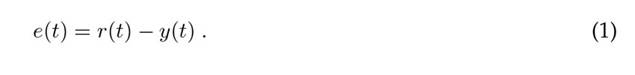
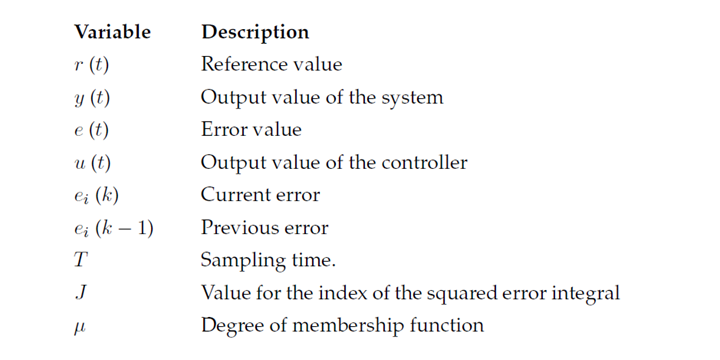
Stage 1: selecting the inputs/outputs for the fuzzy controller A fuzzy controller must operate in real time within a closed loop system. Motor speed data must be collected in y(t) and compared against a reference r(t) to produce an error signal e(t), which can be defined via Eq. 1 (17). Then, e(t) should be minimized while trying to make y(t) ≈ r(t) and used as the input to the fuzzy system, in order to generate a control signal u(t).
Stage 2: fuzzy controller design
Afuzzy system consists of four elements, which coincides with that established by (18) and (19).
1. Fuzzification. e(t) is converted into useful information for the inference mechanism.
2. The inference mechanism emulates human operator decision-making by interpreting and applying knowledge about how best to control the motor speed.
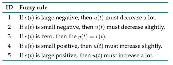
3. Fuzzy rule base. A set of five rules is defined to control the motor speed. The rules presented in Table I were determined by the intuition of a human operator who had previously regulated the voltage to adjust the speed of the DC motor without a controller. These rules use fuzzy logic to quantify the operator’s linguistic description. Their justification is presented below. Rules 1 and 5 (positive or negative large errors). A positive or negative large error indicates a significant deviation between the actual speed y(t) and the reference r(t). This requires a strong control action (drastic increase/decrease of u(t)) to quickly correct the velocity. Rules 2 and 4 (small positive or negative errors). Small errors require smooth adjustments to avoid oscillations and ensure a stable approach to the reference r(t). Rule 3 (zero error). If there is no error, e(t) = 0, the system operates in an ideal state, i.e., y(t) = r(t).
Table I: Fuzzy rule base
4. Defuzzification. Conclusions regarding the inference mechanism are converted into u(t), which is applied as an input to the actuator.
Asillustrated in the blue block of Fig. 1, these four components form the fuzzy system that interacts with the actuator, the DC motor, and the encoder.
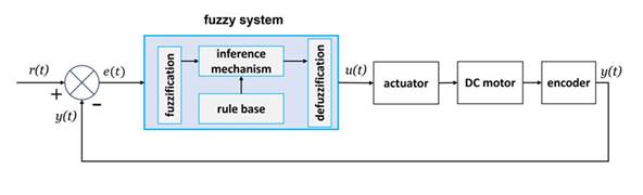
Figure 1: Classical control structure including a fuzzy controller applied to a DC motor
On the other hand, these four elements operate according to the algorithm shown in Fig. 2, wherein y(t), e(t), and u(t) should be transmitted for analysis.
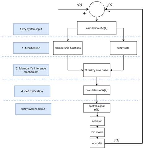
Figure 2: Operating algorithm of the fuzzy system
Stage 3: hardware implementation of the fuzzy controller
The fuzzy system must be implemented electronically on a micro-controller with an analog-to-digital converter to interpret the motor speed in rpm via the included encoder. Furthermore, a pulse width modulation (PWM) module must be included to regulate the voltage by means of a power module, serving as an actuator for the DC motor.
It should be considered that the implementation of this methodology may produce variability in the results due to the physical components used, i.e., the microcontroller micro-controller and its performance, the power module, and the type of motor to be controlled.
Stage 4: membership function customization
The selection of triangle membership functions in a fuzzy logic system depends on the problem under study. Specifically, it depends on the distribution of the available data and the type of output required by the system. For instance, if the data follow a normal distribution, Gaussian membership functions are appropriate. Conversely, if the data tend to a maximum value, triangle membership functions are more suitable. In scenarios where the data are constrained to a specific value, trapezoidal membership functions should be considered. In the context of a DC motor with a maximum value, for instance, triangle membership functions must be employed. These functions are characterized by their simplicity and ease of implementation, requiring only three points for design: two points defining the base of the triangle and one defining its height. These functions allow for controlled overlap between membership functions, enabling the control of the steady-state error and the ISE index. Research works such as those by (14) and (15) have also confirmed the efficacy of triangle membership functions in addressing problems similar to that studied in this work.
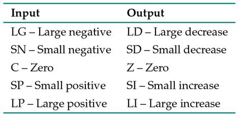
In this method, five triangular membership functions must be defined for the fuzzy output sets of the system, considering the following adjustment parameters: the separation or overlap level, the base length of each triangle, and the operating range. Once these functions have been defined for the fuzzy input sets, seven errors and seven control signals are obtained. The parameters of the functions are adjusted until J is minimized and the steady-state error is zero. For the fuzzy output sets of the system, five overlapping membership functions are also defined. It is worth mentioning that, in each of the settings and experiments to be performed, the membership functions of the output sets must be the same. The linguistic variables considered for the input and output sets are shown in Table II, along with their meaning.
Table II: Linguistic variables defined for the fuzzy system
Controller specifications
Acontrol system must be designed to operate in accordance with an established set of specifications (17,20). Assuming that the control systems are dynamic, their performance can be estimated in terms of their transient response while considering input signals or their behavioral index. Table III shows some examples of performance specifications for a closed-loop controller.
Table III: Examples of specifications for a closed-loop controller
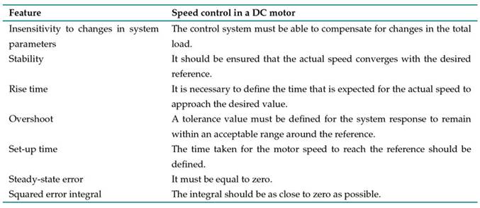
According to (17), a performance index should be easy to estimate either analytically or experimentally. In this vein, this study defines J in Eq. (2) as the squared error integral. As J gets closer to zero, the quality of the system improves. Note that e(t) is the error with respect to time.
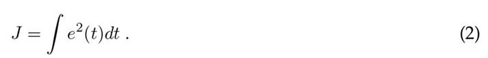
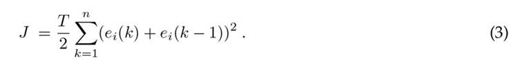
J has been extensively used for deterministic and statistical inputs. To calculate J via a micro-controller algorithm, Eq. (2) must translated into Eq. (3) for digital systems, which can be estimated by using a trapezoidal approximation with multiple iterations (15). Note that ei(k) is the current discretized error, ei(k − 1) is the previous error, and T is the sampling time.
On the other hand, according to (21), an acceptable control behavior can be obtained in the fuzzy system whenthecontrol signal coincides with the error signal. To this effect, e(t) is interpolated through the centroid method, i.e., if e(t) has a degree of membership of 1 to the error fuzzy set, the resulting defuzzified u(t) exactly matches e(t).
Case study
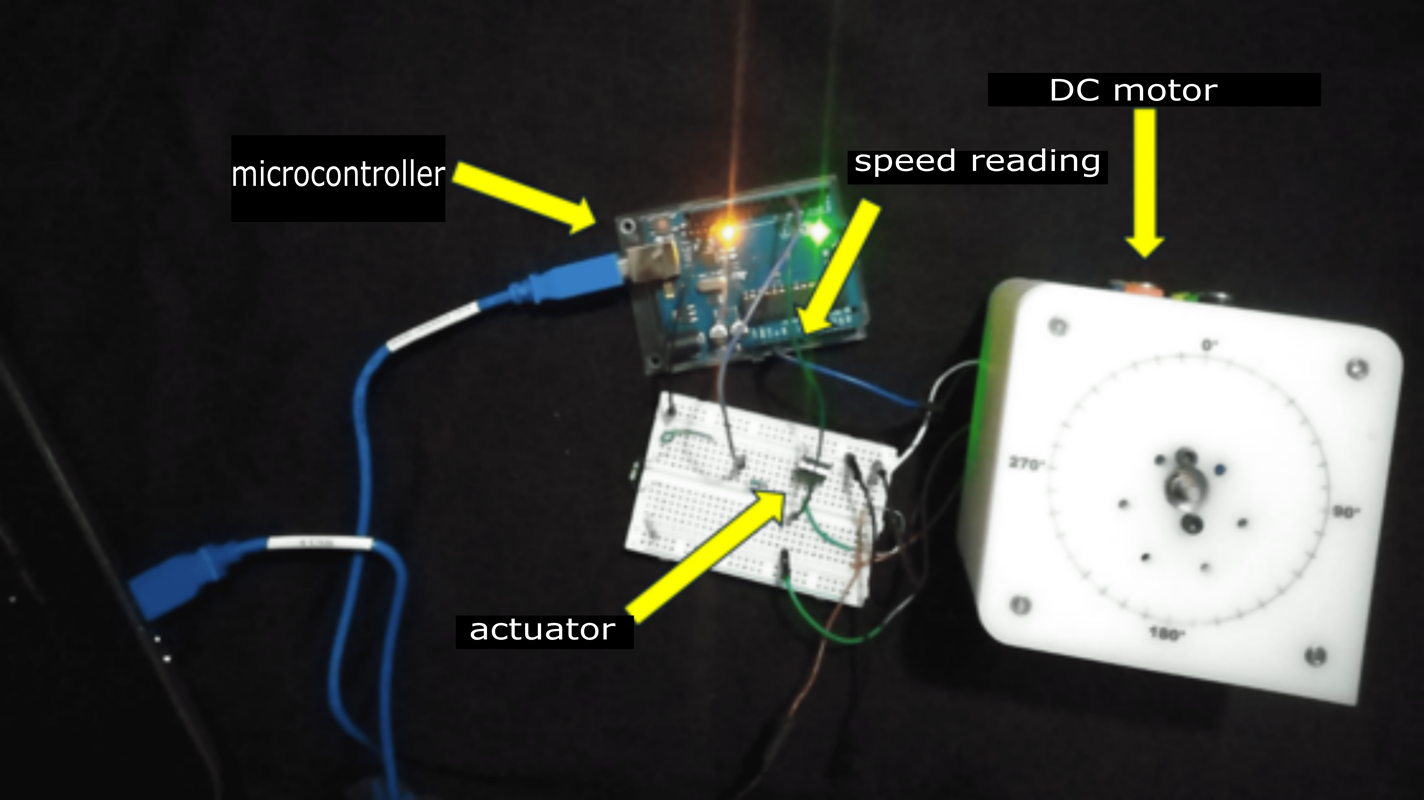
In order to demonstrate the effectiveness of the proposed method, an Atmega328P micro-controller was selected for the experimental setup, given its cost-performance ratio. This micro-controller is based on areduced instruction set computer (RISC) with an in-system programming (ISP) flash memory of 32 KBfeaturing read-while-write capabilities, 1 KB EEPROM, 2 KB SRAM 23general-purpose I/O lines, 32 working registers, three timers/counters with compare modes, internal and external interrupts, a serial programmable USART,anSPIserial port, a 6-channel 10-bit converter, a programmable watchdog timer with an internal oscillator, and five software-selectable power-saving modes. To ensure the efficient execution of the FLC algorithm, the maximum clock frequency was set at 16 MHz. The analog-to-digital converter (ADC) peripheral was used with a resolution of 10 bits, the PWM module with an 8-bit resolution at a frequency of 490 Hz, and the universal asynchronous receiver-transmitter (UART) communicationprotocolataspeedof9600baud.Timer1wasconfiguredtogenerateinterruptionsevery 100 ms to sample the motor speed. Under these conditions, the device exhibited a power consumption of 5 V and a current of ≈ 10 mA. Input A0 captured the motor speed data provided by the encoder in y(t). The encoder had an integrated Hall effect sensor that provided 11 pulses per revolution, a frequency response of 100 kHz with 5 V. Then, y(t) was compared against r(t) to obtain e(t), which wasin turn used as input. The reference speed was defined as r(t) = 140 rpm. This value corresponds to the nominal speed specified by the manufacturer for the DC motor used. In addition, this speed aligns with previous studies on DC motor control, such as those by (8) and (12), who validated their systems at speeds between 100 and 200 rpm. y(t), e(t), and u(t) were then transmitted via serial communication to a spreadsheet for further analysis. The ADC of the Atmega328P micro-controller interpreted the motor speed in rpm using information from the encoder included in the motor. Next, the PD3 pin (a pin configured for PWM) was used to regulate the motor voltage using a TIP31C power transistor as an actuator, operating at 5V and ≈ 10 mA, as well as a GM25-370 motor with 12 V and 0.8 Amps of rated voltage and current. The electronic schematic is shown in Fig. 3(a), and the system implementation is shown in Fig. 3(b).
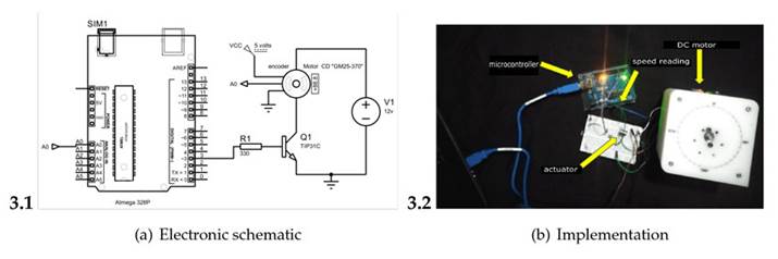
Figure 3: Physical implementation of the fuzzy controller
Fitting of membership functions
The following output membership functions were considered.
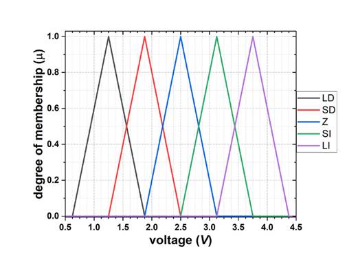
Figure 4: Output membership function
This section presents seven tuning cases used to find the best motor speed control, starting from the imposed reference while seeking to achieve a zero steady-state error and minimize J.

Figure 5: Membership functions using approach 1
-
Fitting 2: bonded sets. In Fig. 6, functions are placed one after another. The distance between the functions is 0 rpm, and the operating range is (-250, 250) rpm, with 100 rpm at each triangle base.

Figure 6: Membership functions using approach 2
-
Fitting 3: slightly overlapping sets. Fig. 7 shows the membership functions with an overlap of 25 rpm. Their operating range is (-200, 200) rpm, and the triangle base is at 100 rpm.
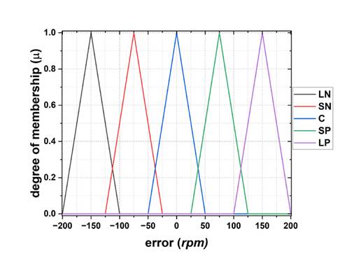
Figure 7: Membership functions using approach 3
-
Fitting 4: medium overlapping sets. In Fig. 8, there is a 50 rpm overlap between functions, and the operating range is (-150, 150) rpm, with 100 rpm at each triangle base.
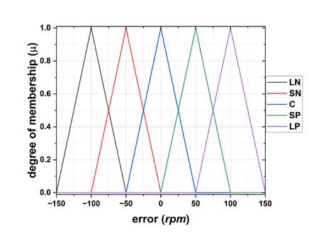
Figure 8: Membership functions using approach 4
-
Fitting 5: heavily overlapping sets. In Fig. 9, a 75 rpm overlap between functions is defined. The operating range is (-100, 100) rpm, with 100 rpm at each triangle base
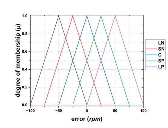
Figure 9: Membership functions using approach 5
-
Fitting 6: center-symmetric sets. In Fig. 10, within the operating range of [-50, 50] rpm, there is an overlap of 25 rpm betweenthe three central functions. The overlap at each triangle base is 50 rpm. However, at the extreme ends, the triangle bases are 100 rpm. The operating range at the left end is [-150,-50] rpm, and, at the right end, it is [50, 150] rpm. The total operating range of this setting is [-150, 150] rpm.
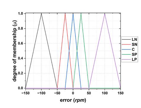
Figure 10: Membership functions using approach 6
-
Fitting 7: asymmetric sets. Finally, in Fig. 11, there is no overlap pattern between functions. Note that the máximum of each membership function is separated by 25 rpm, beginning at 50 rpm, and that the operating range is [-150, 150] rpm.
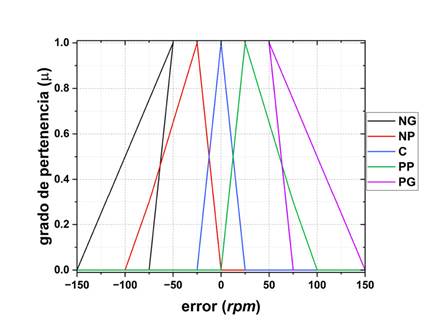
Figure 11: Membership functions using approach 7
Results
Experimental results
As shown in Fig. 1, the fuzzy controller, implemented using an Atmega328P micro-controller, was coupled to the motor using an actuator and an encoder. In this vein, the experiments for each fitting described in Subsection 2.4 were conducted based on the following procedure:
-
In the fuzzy controller program, the motor speed reference was set to 140 rpm.
-
The appropriate membership functions were selected according to each of the seven tuning approaches.
-
On the Atmega328P, the algorithm described in Figure 2 was configured to run the fuzzy controller. Next, the output and reference voltages were acquired, and the error between them and J wascalculated.
-
When the steady-state error was reached (about 25 seconds into the experiment), the experiment was considered complete.
-
The acquired data was confirmed as stored.
Figs. 12-14 show the signals of interest. r(t) = 140 rpm is shown in red, y(t) in black, and e(t) in blue. In Fig. 12, note that e(t) exhibits continuous oscillations throughout the test, indicating that it never reaches a zero steady state. Therefore, the proportion in which the steady state is not reached cannot be quantified. In Fig. 13, e(t) shows no oscillations. At t0, e(t) = 140 rpm, and the final error is 40 rpm, considering a total test time of 25 seconds. This amounts to a steady-state error of 28.57%. Finally, in Fig. 14, e(t) exhibits a final error greater than 52 rpm, i.e., a steady-state error of 37.14%. Note that the control system does not meet the zero steady-state error criterion in these configurations because the membership functions are too far apart or there is not enough overlap between them. According to (21), error interpolation under the fittings indicates poor controller behavior. This is because y(t) does not match r(t).

Figure 12: Results of fitting 1
However, Figs. 15-18 indicate that e(t) ≈ 0 around t ≈ 5 s because y(t) ≈ r(t). Fig. 15 shows slow dynamics, reaching zero error around t = 7.5 s. This is due to the 50 rpm overlap in the membership function configuration. Fig. 16 shows very fast dynamics, reaching zero error at t ≈ 0.3 s. Afterwards, there is a considerable undershoot, reaching a steady state with zero error at t = 5 s, which is due to the 75 rpmoverlap set for the membership functions.
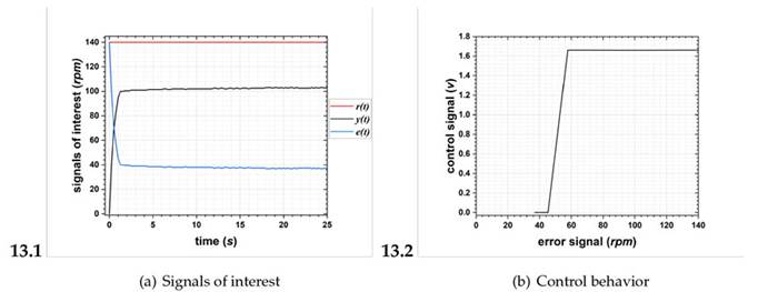
Figure 13: Results of fitting 2
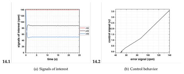
Figure 14: Results of fitting 3

Figure 15: Results of fitting 4
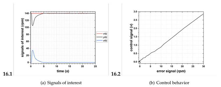
Figure 16: Results of fitting 5
Furthermore, Fig. 17and 18 exhibit fast dynamics in comparison with the previous fittings, and they show avery similar behavior, reaching zero steady-state error at t ≈ 4 s. This is due to the fact that, as shown in Fig. 17, there is an overlap of 25 rpm between the three central functions and no overlap between the side functions. In Fig. 18, there is no overlap pattern, but, in the maxima of the membership functions, there is a separation of 25 rpm.
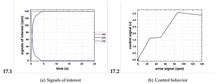
Figure 17: Results of fitting 6

Figure 18: Results of fitting 7
On the other hand, when interpolating e(t) via the centroid method, fittings 5 and 7 (Figs. 16 and 18) exhibited the best control behavior, confirming that y(t) ≈ r(t).
Finally, Fig. 19 shows that J is not minimized under fittings 1 (J =4.1015), 2 (J =0.4689), and 3(J = 0.9702). Conversely, J is indeed minimized with fittings 4 (J = 0.1000), 5 (J = 0.0030), 6 (J = 0.0002), and 7 (J = 0.0500). The fitting that manages to consistently minimize J is fitting 6 (Fig. 17), for which J =0.0002.
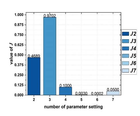
Figure 19: J estimated for the seven fittings
Statistical analysis
Based on the results shown in Fig. 19, fittings 5 and 6 were statistically examined, considering one to ten experiments for each approach. Fig. 20(a) shows the evolution of the mean value of J, and Fig. 20(b) the behavior of its standard deviation. For this statistical analysis, each experiment was performed following the procedure indicated in Section 3.1.
In Fig. 20(a), note that J tends to the mean value J = 2.998×10⁻³, with a standard deviation of 1.474×10⁻⁴ under the approach with fitting 5. Furthermore, Fig. 20(b) shows that J tends to the mean value J = 1.990×10⁻⁴, with a standard deviation of 2.601×10⁻⁵ for fitting 6.
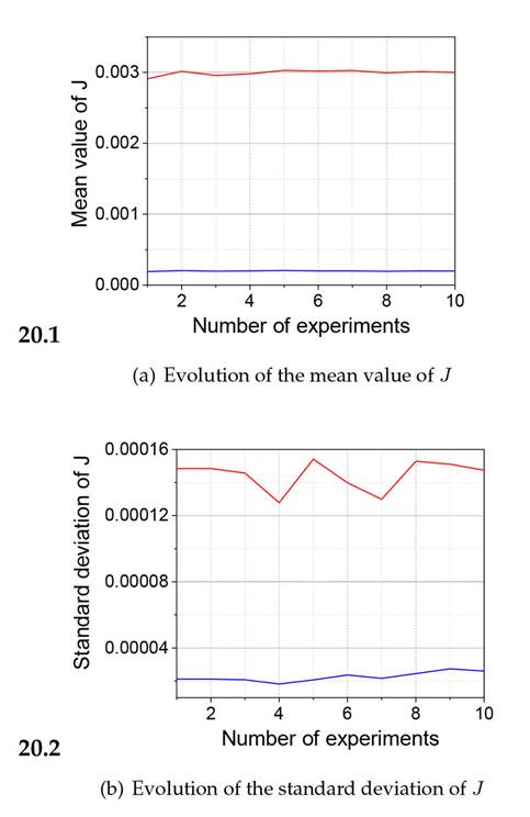
Figure 20: Statistical análisis of fittings 5 (red) and 6 (blue) ,considering one to ten experiments
Discussion
This work experimentally analyzed and evaluated the real implementation of a fuzzy system controlling a DC motor. The evaluation was carried out under different error signal conditions. It should be emphasized that physical implementation is not always possible, but it was in this case thanks to extensive simulation experiments. This study did not endanger people, so no safety measures were required; we were only dealing with a 12 V DC motor. The experimental evaluations provided heuristic insights into the parameter settings of the membership functions, in addition to ensuring the repeatability and reproducibility of the results. Only the variability that could occur in the physical components was considered.
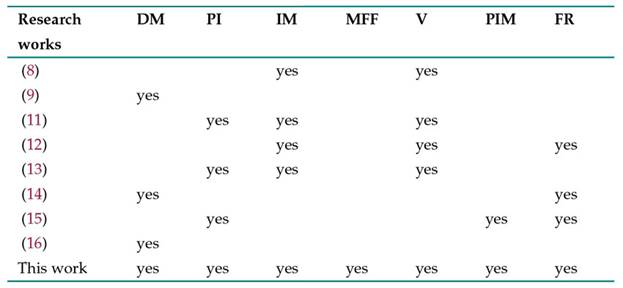
In this sense, Table IV shows some of the contributions of this work when compared to specialized literature. Among said contributions, the following can be highlighted:
-
Unlike proposals such as those by (9), (14), and (16), whose design was limited to three stages (fuzzification, inference mechanism, and defuzzification), our design featured four stages: I/O selection, design (fuzzification, inference mechanism, fuzzy rule base, and defuzzification), physical implementation, and membership function parameterization.
-
We used a performance index to evaluate controller performance. (11), (13), and (15) used the ITAE index. In this work, we experimentally obtained the ISE index.
-
The controllers proposed by (8), (11), 12), and (13) were implemented in high cost micro-controllers or DSPs (digital signal processors) applied to robust motors. In this work, we applied a 328P micro-controller (regarded as low-cost) to a DC motor.
-
Although previous studies have not considered tuning the parameters of the membership functions, in this work, seven parameter configurations for the input membership functions were used.
-
(8), (11), (12), and (13) obtained experimental results with limited metrics. In this work, metrics such as the ISE index, the settling time, and the steady-state error were experimentally obtained.
-
In contrast to (15), who used the ITAE index but failed to minimize the error below a value of 1, in this work, six out of the seven fittings managed to reduce the ISE below this value, and the sixth configuration minimized it to 0.0002.
-
Similar to (12), (14), and (15), this work used a low number of rules; only five were contained in the rule base.
Note: DM=design methodology, PI = performance index, IM = physical implementation, MFF = membership function fitting, V = validation, PIM = performance index minimization, and FR = low number of rules
Table IV: Comparison of this work with others reported in literature
The main advantage of this methodology was its ability to systematically adjust the parameters of the input membership functions in six out of the seven case studies, optimizing the controller by means of quantitative metrics such as the steady-state error, the control behavior, and the ISE (with a minimum J =0.0002). This methodology ensured the minimization of J. An inherent limitation of the proposed methodology is that its replication in other systems may generate variable results, since the performance of the fuzzycontroller critically depends on the specific characteristics of the physical plant (nominal motor speed, encoder characteristics) and the electronic components used (actuators, sensors). This work could evolve towards the design and implementation of an adaptive fuzzy controller, to whichneural network tools or genetic algorithms could be incorporated, with the purpose of facilitating automatic parameter adjustment within the membership functions, optimizing the controller to match the dynamic responses of the plant or system under control. The proposed method can be extended to a wide range of control problems. Its potential applications include temperature control in ovens, drone stabilization, automatic irrigation control in agriculture, and level and flow control in tanks. On a small scale, the system could be applied in autonomous precision systems such as drones, mobile robots, vehicles that follow lines, or robotic arms. On a larger scale, its implementation in the field of electromobility, e.g., speed regulation in scooters, electric bicycles, or small vehicles, is also a viable option, as evidenced by studies such as (2) and (9).
Conclusions
This study shows how fuzzy logic allows implementing the knowledge of a human operator in a control system. In this case, a fuzzy controller was used as an example to control the speed of a DC motor. The application of the proposed methodology ensured that the designed control system would work as expected, which was achieved by gradually finding the conditions that led to zero steady-state error. This corresponds to the control specifications in Table III.
In addition, some modifications to the fuzzy controller can be considered. For example, the parameters of the associated output membership functions could be adjusted with respect to the voltage provided by the micro-controller. Other types of membership functions (trapezoidal, bell functions) could be used, although they may be more complicated to implement. The choice of membership function can affect the response of the system to the action of the controller. The design of fuzzy controllers could also aim for other conditions such as stability, i.e., when the system response is free from oscillations; it could consider the response speed, which refers to how quickly the system reaches the desired value after a change in the imposed reference signal; or it could focus on ease of implementation and the tuning of the controller in the real system, since a controller that is easy to implement and tune can save time and resources.
Acknowledgements
Acknowledgment
D. Aguilar-Torres (CVU-829790), D. Gutiérrez-Rosales (CVU-1269306), J. Jimenez-Ramirez (CVU-2063181), and Ezequiel Rincón-Canalizo (CVU-2063199) are grateful for the grant provided by Secretaría de Ciencia, Humanidades, Tecnología e Innovación (SECIHTI, Mexico).
References
Nomenclature
License
Copyright (c) 2025 David Guti´errez-Rosales, Arturo Cordero-Guillén, Omar Jiménez-Ramírez, Ruben Vazquez-Medina

This work is licensed under a Creative Commons Attribution-NonCommercial-ShareAlike 4.0 International License.
![]()
From the edition of the V23N3 of year 2018 forward, the Creative Commons License "Attribution-Non-Commercial - No Derivative Works " is changed to the following:
Attribution - Non-Commercial - Share the same: this license allows others to distribute, remix, retouch, and create from your work in a non-commercial way, as long as they give you credit and license their new creations under the same conditions.

2.jpg)