DOI:
https://doi.org/10.14483/23448393.22926Published:
2025-08-01Issue:
Vol. 30 No. 2 (2025): May-AugustSection:
Mechanical EngineeringTheoretical-Experimental Modal Analysis of a Flexible Rotor Based on the Jeffcott Model
Análisis modal teórico-experimental de un rotor flexible basado en el modelo de Jeffcott
Keywords:
MAC, vibration mode shapes, flexible rotors, Jeffcott rotor, Experimental Modal Analysis, Theoretical Modal Analysis, natural frequencies (en).Keywords:
Análisis Modal Experimental, Análisis Modal Teórico, frecuencias naturales, MAC, modos de vibración, rotores flexibles, rotor de Jeffcott (es).Downloads
References
H. G. Sánchez-Acevedo, “Modelo analítico para el estudio de la torsión en rotores flexibles,” Rev. UIS Ing., vol. 9, no. 1, pp. 69–76, 2010.
V. Gagnol, T.-P. Le, and P. Ray, “Numerical and experimental high speed machining spindle-tool modal characterization (dynamics of machine components),” in Proc. Asian Conf. Multibody Dyna., 2010, pp. 57636-1–57636-11. https://doi.org/10.1299/jsmeacmd.2010.5._57636-1_
Z. Huang and B. Han, “Effective approach for calculating critical speeds of high‐speed permanent magnet motor rotor‐shaft assemblies,” IET Electr. Power Appl., vol. 9, no. 9, pp. 628–633, Nov. 2015. https://doi.org/10.1049/iet-epa.2014.0503
H. G. Sánchez, F. R. Nova, and O. A. González-Estrada, “Implementation of the operational modal analysis technique in a power transmission shaft,” J. Phys. Conf. Ser., vol. 1247, no. 1, art. 012032, Jun. 2019. https://doi.org/10.1088/1742-6596/1247/1/012032
B. F. Morales-Hernández, “Metodología para el ajuste y validación del modelo numérico de un rotor de Jeffcott, mediante el uso de funciones de respuesta en frecuencia (FRF),” Master’s thesis, Universidad Industrial de Santander, Bucaramanga, Colombia, 2023.
Z. Huang, B. Han, and Y. Le, “Modeling method of the modal analysis for turbomolecular pump rotor blades,” Vacuum, vol. 144, pp. 145–151, Oct. 2017. https://doi.org/10.1016/j.vacuum.2017.07.029
H. H. Jeffcott, “The lateral vibration of loaded shafts in the neighbourhood of a whirling speed.—The effect of want of balance,” Lond. Dub. Edim. Phil. Mag. J. Sci., vol. 37, pp. 304–314, 1919. https://doi.org/10.1080/14786440308635889
A. Malgol, K. P. Vineesh, and A. Saha, “Investigation of vibration characteristics of a Jeffcott rotor system under the influence of nonlinear restoring force, hydrodynamic effect, and gyroscopic effect,” J. Brazilian Soc, Mech. Sci. Eng., vol. 44, no. 3, p. 105, 2022. https://doi.org/10.1007/s40430-021-03277-x
J. Liu, C. Tang, and G. Pan, “Dynamic modeling and simulation of a flexible-rotor ball bearing system,” J. Vibr. Control, vol. 28, no. 23–24, pp. 3495–3509, Dec. 2022. https://doi.org/10.1177/10775463211034347
A. Blanco-Ortega, F. Beltrán-Carbajal, G. Silva-Navarro, and H. Méndez-Azúa, “Control de vibraciones en maquinaria rotatoria,” Rev. Ibero. Autom, Infor, Ind. RIAI, vol. 7, no. 4, pp. 36–43, Oct. 2010. https://doi.org/10.1016/s1697-7912(10)70058-3
E. Sarrouy, O. Dessombz, and J.-J. Sinou, “Stochastic analysis of the eigenvalue problem for mechanical systems using polynomial chaos expansion— Application to a finite element rotor,” J. Vibr. Acoust., vol. 134, no. 5, art. 051009, Oct. 2012. https://doi.org/10.1115/1.4005842
J. Páez Chávez, V. Vaziri Hamaneh, and M. Wiercigroch, “Modelling and experimental verification of an asymmetric Jeffcott rotor with radial clearance,” J. Sound Vibr., vol. 334, pp. 86–97, Jan. 2015. https://doi.org/10.1016/j.jsv.2014.05.049
Y. M. Ameen and J. K. Ali, “Theoretical and experimental modal analysis of circular cross-section shaft,” IOP Conf. Ser. Mater. Sci. Eng., vol. 745, no. 1, art. 012066, Feb. 2020. https://doi.org/10.1088/1757-899X/745/1/012066
A. Kandil, “Investigation of the whirling motion and rub/impact occurrence in a 16-pole rotor active magnetic bearings system with constant stiffness,” Nonlinear Dyna., vol. 102, no. 4, pp. 2247–2265, Dec. 2020. https://doi.org/10.1007/s11071-020-06071-x
A. Kandil and Y. S. Hamed, “Tuned positive position feedback control of an active magnetic bearings system with 16-poles and constant stiffness,” IEEE Access, vol. 9, pp. 73857–73872, 2021. https://doi.org/10.1109/ACCESS.2021.3080457
R. J. Allemang, “The modal assurance criterion–Twenty years of use and abuse,” Sound Vibr., vol. 37, pp. 14–23, 2003. https://www.sandv.com/downloads/0308alle.pdf
C. Chen, P. Duffour, and P. Fromme, “Modelling wind turbine tower-rotor interaction through an aerodynamic damping matrix,” J. Sound Vibr., vol. 489, art. 115667, Dec. 2020. https://doi.org/10.1016/j.jsv.2020.115667
L. Cveticanin, “Free vibration of a Jeffcott rotor with pure cubic non-linear elastic property of the shaft,” Mech. Mach. Theory, vol. 40, no. 12, pp. 1330–1344, Dec. 2005. https://doi.org/10.1016/j.mechmachtheory.2005.03.002
T. H. EL-MAHDY and R. M. GADELRAB, “Free vibration of unidirectional fiber reinforcement composite rotor,” J. Sound Vibr., vol. 230, no. 1, pp. 195–202, Feb. 2000. https://doi.org/10.1006/jsvi.1999.2573
J. Warminski, L. Kloda, and S. Lenci, “Nonlinear vibrations of an extensional beam with tip mass in slewing motion,” Meccanica, vol. 55, no. 12, pp. 2311–2335, Dec. 2020. https://doi.org/10.1007/S11012-020-01236-9/TABLES/2
J. Taghipour, M. Dardel, and M. H. Pashaei, “Nonlinear vibration mitigation of a flexible rotor shaft carrying a longitudinally dispositioned unbalanced rigid disc,” Nonlinear Dyna., vol. 104, no. 3, pp. 2145–2184, May 2021. https://doi.org/10.1007/S11071-021-06428-W/METRICS
R. Zaradnik, S. Raichman, and A. E. Mirasso, “Comparación de diversas matrices de masas concentradas con similitud de modos propios,” Mecánica Computacional, vol. 28, no. 10, pp. 853-869. https://www.researchgate.net/publication/329170895_COMPARACION_DE_DIVERSAS_MATRICES_DE_MASAS_CONCENTRADAS_CON_SIMILITUD_DE_MODOS_PROPIOS
Y. Xu, J. Zhou, L. Di, C. Zhao, and Q. Guo, “Active magnetic bearing rotor model updating using resonance and MAC error,” Shock Vibr., vol. 2015, pp. 1–9, 2015. https://doi.org/10.1155/2015/263062
How to Cite
APA
ACM
ACS
ABNT
Chicago
Harvard
IEEE
MLA
Turabian
Vancouver
Download Citation
Recibido: 21 de noviembre de 2024; Aceptado: 20 de junio de 2025
Abstract
Context:
Rotating equipment that operates at high speeds or handles significant loads is designed based on the concept of flexible shafts. This is the case with turbines, compressors, and turbopumps, among others. The theoretical-experimental modal analysis of these shafts is crucial for ensuring a safe and efficient operation, as well as for identifying appropriate maintenance strategies.
Method:
In this work, we perform both theoretical and experimental modal analyses of an isotropic flexible rotor based on the Jeffcott model. The theoretical modal analysis is carried out using a numerical model with conditions similar to those of the experimental analysis. The results are compared using the modal assurance criterion (MAC). The validated numerical model enables the evaluation of eigenfrequencies and their associated modal shapes.
Results:
The first two bending natural modes of the flexible rotor were obtained from the theoretical and experimental modal analysis, and the mode shapes and natural frequencies were determined. The mode shapes were correlated, exhibiting a correlation value greater than 88%, thus validating the numerical model.
Conclusions:
This approach not only enhances the understanding of the shaft’s dynamic response but also contributes to improved decision-making during the design and operation stages of rotating systems in various industrial applications.
Keywords:
experimental modal analysis, theoretical modal analysis, natural frequencies, MAC, vibration mode shapes, flexible rotors, Jeffcott rotor.Resumen
Contexto:
El equipo rotativo que opera a altas velocidades o maneja cargas significativas se diseña con base en el concepto de ejes flexibles. Este es el caso de las turbinas, los compresores y las turbobombas, entre otros. El análisis modal teórico-experimental de estos ejes es esencial para garantizar una operación segura y eficiente, así como para identificar estrategias de mantenimiento adecuadas.
Método:
En este trabajo desarrollamos análisis modales tanto teóricos como experimentales de un rotor flexible isotrópico basado en el modelo de Jeffcott. El análisis modal teórico se realiza utilizando un modelo numérico con condiciones similares a las del análisis experimental. Los resultados se comparan utilizando el criterio de aseguramiento modal (MAC). El modelo numérico validado permite evaluar las frecuencias propias y sus formas modales asociadas.
Resultados:
Se obtuvieron los dos primeros modos naturales de flexión del rotor flexible del análisis modal teórico y experimental, y se determinaron las formas modales y las frecuencias naturales. Las formas modales estuvieron correlacionadas, obteniendo un valor de correlación superior al 88%, lo que valida el modelo numérico.
Conclusiones:
Este enfoque no solo mejora la comprensión de la respuesta dinámica del eje, sino que también contribuye a mejorar la toma de decisiones durante las etapas de diseño y operación de sistemas rotativos en diversas aplicaciones industriales.
Palabras clave:
análisis modal experimental, análisis modal teórico, frecuencias naturales, MAC, modos de vibración, rotores flexibles, rotor de Jeffcott.Introduction
Rotating machines operating at high speeds and loads, such as turbines, compressors, and turbopumps, are typically designed with flexible shafts 1. Analyzing the natural frequencies and mode shapes of these systems is essential for ensuring their safe and efficient operation. Theoretical and experimental modal analyses have become key tools for identifying critical speeds and defining appropriate maintenance strategies 2,3.
This work conducts a theoretical and experimental modal analysis on a Jeffcott-based rotor. A numerical model based on the finite element method (FEM) is used to simulate the rotor’s conditions, and the results are compared against experimental data using the modal assurance criterion (MAC). This criterion facilitates the validation of the numerical model by assessing its consistency with the rotor’s dynamic behavior.
The application of theoretical and experimental modal analysis to rotors has been an active research area in structural and mechanical dynamics, particularly in rotating machinery 4)- (6. Due to its simplicity and its ability to represent the dynamic behavior of more complex systems, the Jeffcott rotor 7 has been widely used in similar studies to analyze the vibration responses of rotating systems 8. Several studies have developed numerical models to simulate the behavior of its shafts under varying load and rotational speed conditions 9,10. In recent years, simulation tools such as the FEMhaveenabled a precise analysis of the dynamic behavior of flexible shafts 11. These tools make it possible to accurately determine natural frequencies and mode shapes, which is essential for avoiding resonance issues during the operation of rotating machinery 9. Additionally, advancements in sensors and excitation systems (e.g., shakers) have significantly improved the quality of the results obtained through experimental modal analysis.
Numerical modal validation requires the comparison of numerical results against experimental data 5,12. In this context, experimental modal analysis (EMA) is a highly useful tool. EMA is a test that allows acquiring modal information about an element, including the frequency response to the applied excitation forces 13. Comparing the outcomes of theoretical modal analysis (TMA) against those of EMAallowsvalidating numerical results, ensuring an adequate correlation between the vibration mode shapes obtained in both analyses. This approach has led to a better understanding of the behavior of rotating systems, contributing to improved design and maintenance strategies for industrial equipment.
In addition to classical approaches to rotor modeling and experimental validation, several studies have addressed more advanced rotor systems using nonlinear dynamics and active control strategies. For instance, 14) investigated the whirling behavior and rub/impact phenomena of a 16-pole rotor supported by active magnetic bearings (AMBs), employing the multiple scales method to analyze the system’s nonlinear response. More recently, 15 proposed a tuned positive position feedback (TPPF) control strategy to mitigate vibrations in a magnetically suspended rotor, demonstrating the effectiveness of control design in stabilizing rotor motion under various conditions. Although these studies focus on AMB- supported systems, they provide valuable insights into rotor dynamics beyond the scope of linear free-free configurations.
This research was conducted in three stages: 1) numerical model implementation, 2) experimental modal analysis, and 3) model validation using the MAC. The numerical model of the rotor was developed based on the FEM. The process began by selecting the coordinate system and defining the degrees of freedom. Next, the type and number of elements for the rotor were discretized to strike a balance between accuracy and computational cost. Through this discretization, the mass and stiffness matrices were assembled to describe the system’s dynamic behavior. Subsequently, the eigenvalue problem was solved to numerically obtain the rotor’s natural frequencies and mode shapes. Following this, EMA wascarried out. Multiple equidistant points were marked on the rotor, which was suspended by elastics to simulate free-free boundary conditions. An accelerometer was placed at a reference point, and each marked point was impacted with a hammer. These measurements were used to calculate the frequency response functions, from which modal identification was performed. Finally, the rotor’s numerical model was validated by correlating the results of the experimental and numerical modal analyses. The degree of similarity between modes was determined using the MAC, which quantifies the agreement between experimental and numerical mode shapes 16.
Numerical model
The rotor analyzed in both the numerical and experimental studies consisted of a steel shaft with a centrally mounted aluminum disk. This simple and symmetric configuration is representative of the basic rotor geometries that are often used in rotordynamic studies, and it allows for a clear identification of bending modes and natural frequencies. The geometric dimensions and material properties of both components are summarized in Table I.
Table I: Geometric dimensions and mechanical properties of the shaft and disk

The numerical model was implemented and solved in the MATLAB programming environment. This formulation is based on the equation of motion for a forced system 17, which governs the rotor’s dynamic behavior and is expressed in matrix form, as shown in Eq. (1).

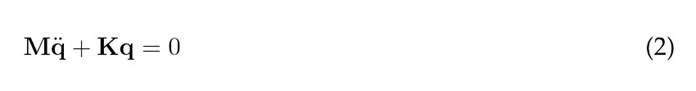
where M represents the mass matrix, C the damping matrix, K the stiffness matrix, f the force vector, q the displacement vector, ˙q the velocity vector, and ¨q the acceleration vector. To study the free vibrations of the Jeffcott rotor, damping is neglected, and the external force is set to zero. The resulting equation is known as the equation of motion for a free system 18,19 and is presented in Eq. (2).
Using the defined equation of motion, the shaft is discretized into eight linear beam elements, each consisting of two nodes and eight degrees of freedom (DOF), four per node, two translational (v and ϑ) and two rotational (θ and ϕ). Axial DOF are not considered, as this study focuses on lateral vibrations. Fig. 1 illustrates the reference coordinates and the associated DOF.
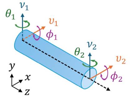
Figure 1: DOFs and reference coordinates
Based on the rotor discretization, the element mass matrix Me and the stiffness matrix Ke for each rotor elementarecomputedusingtheenergymethodandEuler-Bernoullibeamtheory.Thisformulation neglects both rotary inertia and shear deformation, which is appropriate for the slender shaft geometry considered in this work 5, (20, (21). The resulting matrices are shown in Eqs. (3) and (4). Afterwards, the element matrices are assembled according to their corresponding DOF ,yielding the global mass M and stiffness K matrices.
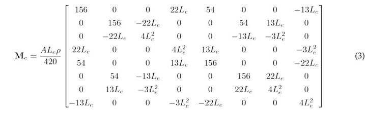
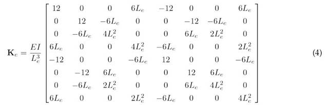
where A denotes the cross-sectional area, L e the length of the element, ρ the material density, E the modulus of elasticity, and I the element’s second moment of inertia. The mass contribution of the disk is incorporated into the overall mass matrix as a concentrated (or point) mass 22 at the disk’s location node - specifically at node 5. The disk mass matrix is presented in Eq. (5).
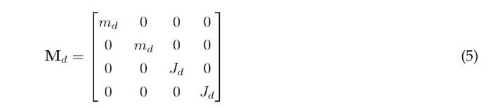
where m d is the mass of the disk and J d is the moment of inertia of the disk perpendicular to the axis of rotation. With the global mass matrix M and stiffness matrix K established, the eigenvalue and eigenvector problem is solved as shown in Eq. (6).
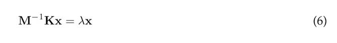
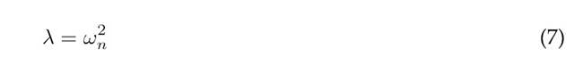
wherexrepresentstheeigenvectors ofthesystemassociatedwiththemodeshapes,andλrepresents the eigenvalues, which are related to the natural frequencies ωn, as shown in Eq. (7). In this work, the eigenvalue problem was solved using MATLAB’s eig function.
Experimental modal analysis
To conduct the EMA, the shaft was divided into eight equidistant segments, resulting in nine measurement positions (Fig. 2). The selection of measurement and excitation points was based on a preliminary numerical modal analysis (NMA) of the first two bending modes. From this analysis, point 6 waschosenasthereference accelerometer position, as it corresponds to an antinode and avoids nodes, thus ensuring an effective capture of the response. All nine positions were used as points for excitation with the impact hammer, in order to ensure an adequate modal coverage.
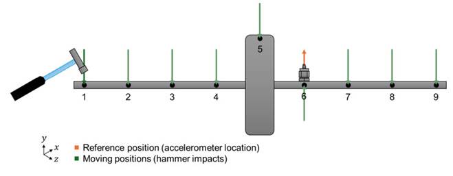
Figure 2: Configuration of the EMA measurement setup
It should be noted that this type of experimental test requires specific planning for each rotor configuration. The location of the accelerometers, excitation points, and frequency range must consider prior numerical simulations and the specific geometric and dynamic characteristics of the rotor under study. In this case, the shaft was suspended using elastic bands to approximate free-free boundary conditions (Fig. 3).
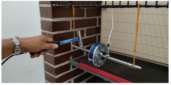
Figure 3: Experimental setup showing the suspended shaft, accelerometer, and impact hammer for simulating free-free boundary conditions
Additionally, Fig. 4 presents the data acquisition system used for the test, including the measurement software interface and the vibration analyzer equipment.
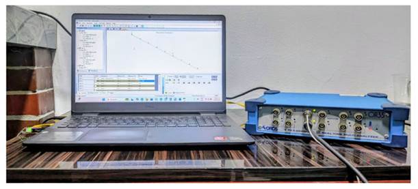
Figure 4: Data acquisition system used in the experimental tests, including the software interface and vibration analyzer
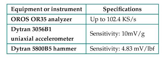
The equipment and instrumentation used for the EMA, along with their main specifications, are listed in Table II.
Table II: General specifications of the equipment and instruments used in the EMA
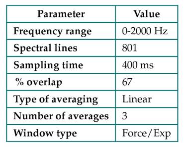
The OROS modal software was used to acquire and process data, as well as to perform the EMA. The main configuration parameters related to the acquisition and processing of the response and excitation force signals are shown in Table III.
Table III: Configuration parameters for the EMA in the OROS modal software
The modal characteristics were calculated from the frequency response functions (FRF) over the entire measurement range. This was done using the broadband method, which employs a robust modal identification algorithm. To apply this method, a frequency range of 167.5-1125 Hz was selected from the modal indication function (MIF) plot. This selection was made by identifying the most prominent peaks and adjusting the limits to the troughs at the beginning of the first peak and at the end of the last peak of interest (Fig. 5).
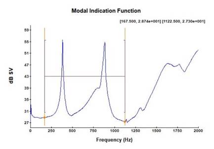
Figure 5: MIF of the EMA of the rotor
Once the frequency range had been established, modal identification began by obtaining the poles from the stabilization diagram (Fig. 6). The poles were determined by defining two preset modes, a minimum of 16 modes, and a range of 12 modes. The two frequencies that showed the greatest coincidence with the peaks of the MIF and the frequencies of the stable poles, identified by the green s in the stabilization diagram, were selected.
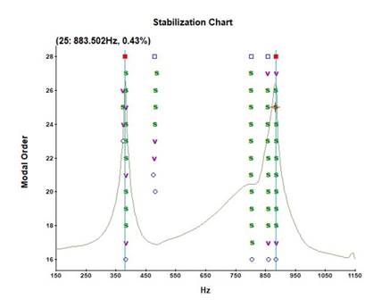
Figure 6: Mode stabilization chart
With the selected frequencies, the deflection shapes were calculated, and the synthesized frequency response function (SFRF) was obtained (Fig. 7). The graph shows the fit, regarding both peak location and phase, of the selected eigenfrequencies between the synthesized FRF and the frequency response function obtained from the measurements.
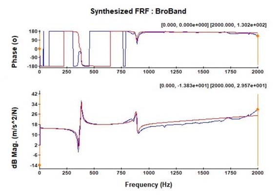
Figure 7: Frequency response function synthesized using the broadband method
Model validation
The numerical model was validated using the MAC. This method correlates the modes obtained from two different sources (numerical-numerical, numerical-experimental, or experimental-experimental). The MAC value indicates the degree of correlation and correspondence between the two sets of modes. It ranges from 0 to 1, with a value of 1 representing the highest degree of correlation between the modes. The MAC 16 is defined in Eq. (8).

where ψx is the experimental modal vector, and ψa is the numerical modal vector for mode i. The superscript T denotes the conjugate transpose of the modal vector.
Results analysis
The deflection shapes (or modal shapes) obtained from the numerical model exhibit the typical morphological characteristics of bending modes. Specifically, the first mode shows two nodes and three antinodes, while the second mode has three nodes and four antinodes. The frequencies associated with these modesare 368.7 and 841 Hz ,respectively, whichconfirmtherotor’sabilitytooperateacross awide range of speeds. The modal shapes, along with the natural frequencies corresponding to the first two bending modes of the rotor, are shown in Fig. 8, as obtained from the implemented numerical model.
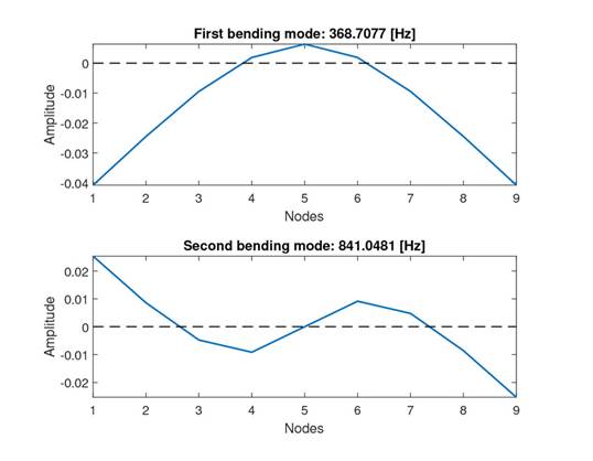
Figure 8: First and second rotor bending modes obtained from the numerical model
The modalshapes obtained from the EMAreveal one modecorresponding to the first rotor bending mode and another associated with the second bending mode. The natural frequencies associated with these modes are 381.2 and 883.85 Hz. Based on these results, the rotor’s safe operating speed range is limited to approximately 0-18,300 RPM, i.e., 20% below the first bending natural frequency. This prevents the rotor from operating near the critical speed. The deflection of the first two modes shows a slight asymmetry at the ends, which may be caused by changes in stiffness and mass in the area where the keyseat or wedge is located (on the left side of the rotor). The experimental modal shapes and their natural frequencies are shown in Fig. 9.
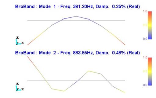
Figure 9: First and second rotor bending modes obtained from the EMA
The results of applying the MAC show a high degree of correlation and correspondence between the modes obtained from the EMA and those from the numerical model. The first bending mode shows a 99.78% correlation, while the second bending mode exhibits an 88.66% correlation. These correlation and correspondence values validate the implemented numerical model. The results of the MACapplication are shown in Fig. 10.
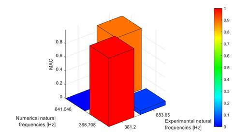
Figure 10: MAC between the experimental and numerical rotor modes
While updating the active magnetic bearing rotor model, 23 used the MAC as part of the updating function. The values obtained were close to 1, exceeding 97.9% and approaching 100% for the first modes. The higher correlation of mode shapes compared to our results can be attributed to the larger number of nodes in the EMA and the greater number of DOF in the numerical model, along with the precision of the material’s mechanical properties defined in the numerical model.
Conclusions
According to the MAC method, the numerical model of the rotor shows a correlation andagreement of over 88% with the results from the EMA for the analyzed bending natural frequencies. These results validate the implemented model.
The first two bending modes of the shaft have natural frequencies of 381.2 and 883.85 Hz, and their deflection shapes exhibit the typical morphological characteristics of this type of shaft or beam. The relatively high values of the natural frequencies allow the shaft to operate across a wide speed range, up to 18,297 rpm, ensuring that the shaft operates below 20% of the first natural bending frequency.
The use of linear beam elements facilitates the implementation of the rotor’s numerical model, given their ability to adapt to the geometry and behavior of the shafts, offering an optimal balance between accuracy and computational efficiency. This allows simulating the Dynamic behavior of rotating structures, such as flexible shafts, at a relatively low computational cost.
References
License
Copyright (c) 2025 Javier Ruíz-Rodríguez, Brian Farid Morales-Hernández, Heller Guillermo Sánchez-Acevedo

This work is licensed under a Creative Commons Attribution-NonCommercial-ShareAlike 4.0 International License.
![]()
From the edition of the V23N3 of year 2018 forward, the Creative Commons License "Attribution-Non-Commercial - No Derivative Works " is changed to the following:
Attribution - Non-Commercial - Share the same: this license allows others to distribute, remix, retouch, and create from your work in a non-commercial way, as long as they give you credit and license their new creations under the same conditions.

2.jpg)