DOI:
https://doi.org/10.14483/23448393.17076Publicado:
2020-10-14Número:
Vol. 25 Núm. 3 (2020): Septiembre - DiciembreSección:
Sección Especial: Mejores artículos extendidos - WEA 2020Electronic Device for Satellite Backup of Automatic Vehicle Location Equipment Using the Iridium Network
Dispositivo electrónico para respaldo satelital de equipos de localización vehicular automática, utilizando la red Iridium
Palabras clave:
Equipos AVL, canal de respaldo satelital, red Iridium (es).Palabras clave:
AVL equipment, satellite backrest, Iridium network (en).Descargas
Referencias
Ministerio de Transporte. Concepto de operaciones - dispositivo AVL, 2016. [Online]. Available: https://www.mintransporte.gov.co/descargar.php?idFile=14648
J. Wang, L. Lei, and Z. Mingtian, “Topological dynamics characterization for LEO satellite networks”, Comp. Net., vol. 51, no. 1, pp. 43-53, 2017. doi: 10.1016/j.comnet.2006.04.010
T. Henderson and R. Katz, “Network simulation for LEO satellite networks”, presented at 18th AIAA Int. Comm. Sat. Sys. Conf. (ICSSC), Reston, VA, USA, 2000, pp. 10-14. doi: 10.2514/6.2000-1237
T. Henderson, “LEO Satellite Networks”, in Wiley Encyclopedia of Telecommunications, J.G. Proakis, Ed., Hoboken, NJ, USA. Wiley & Sons Inc., 2003. doi: 10.1002/0471219282.eot187
Iridium, The Global Network: Ground Infrastructure. Iridium’s extensive, interconnected ground network provides multiple layers of redundancy and back-up systems for all critical functions to ensure high network reliability. Iridium Communications Inc.; 2012. [Online]. Available: https://apollosat.com/intel/iridium-networks-ground-infrastructure/
Iridium, The Global Network: Satellite Constellation. Iridium’s cross-linked LEO constellation architecture provides multiple layers of resiliency and redundancy to provide industry-leading network reliability, Iridium Communications Inc, 2012. [Online]. Available: https://apollosat.com/intel/iridium-networks-ground-infrastructure/
Iridium Communications Inc., “Iridium 9603(N) SBD Transceiver, Developer’s Guide”, Rev 2.1., Iridium Communications Inc., McLean, VA, USA, 2012.
Iridium Communications Inc., “Iridium 9603N and 9602N SBD Transceiver Antenna Connections”, Iridium Communications Inc., McLean, VA, USA, 2012.
Iridium Communications Inc., “Iridium Short Burst Data Service, Developer’s Guide. Release 3.0.”, Iridium Communications Inc., McLean, VA, USA, 2012.
ICAO “Technical Manual for Iridium Aeronautical Mobile Satellite (Route) Service”, Draft v1.1, ICAO, Montreal, Canada, 2006.
Generic Standard on Printed Board Design, IPC -2221. Bonn, Germany, 1998.
Cómo citar
APA
ACM
ACS
ABNT
Chicago
Harvard
IEEE
MLA
Turabian
Vancouver
Descargar cita
Recibido: 1 de junio de 2020; Revisión recibida: 31 de agosto de 2020; Aceptado: 15 de septiembre de 2020
Abstract
Context:
This paper presents the design and development of an electronic device that operates as a satellite backup channel for automatic vehicle location (AVL) equipment, whose only communication channel is the cellular network.
Method:
The design, manufacture and assembly of the hardware followed 4 phases, and it was aligned with the IPC 2221 standard. This allowed improving the design experience and guaranteed the correct electrical operation in the final product.
Results:
The information sent by the developed device corresponds to the data generated by the AVL device, which indicates that the information processing was correctly designed. Additionally, it was possible to obtain a functional and versatile device in which the blocks were correctly integrated; its firmware was designed to receive future updates that improved and expanded its capacity and compatibility with other devices.
Conclusions:
The final product, which works with the Iridium network, seeks to satisfy the technological requirements of the freight transport sector in Colombia with a low-cost, versatile, and easily integrated solution. The implementation of this type of technologies expands the capacity of tracking mobile assets, even in places where there is no cellular network coverage.
Keywords:
AVL equipment, satellite backrest, Iridium network.Resumen
Contexto:
Este articulo presenta el diseño y desarrollo de un dispositivo electrónico, que funciona como canal de respaldo satelital para equipos de localización vehicular automática (AVL), cuyo único canal de comunicación es la red celular.
Método:
El diseño, fabricación y ensamblaje del hardware siguió cuatro fases y estuvo alineado con el estándar IPC 2221. Esto permitió mejorar la experiencia del diseño y garantizó el correcto funcionamiento eléctrico en el producto final.
Resultados:
La información enviada por el dispositivo desarrollado corresponde a los datos generados por el dispositivo AVL, lo que indica que el procesamiento de la información fue diseñado correctamente. Además, fue posible obtener un dispositivo funcional y versátil cuyos bloques se integraron correctamente; su firmware fue diseñado para recibir futuras actualizaciones que mejoraran y ampliaran su capacidad y compatibilidad con otros dispositivos.
Conclusiones:
El producto final, que opera con la red Iridium, busca satisfacer las necesidades tecnológicas del sector de transporte de carga en Colombia con una solución versátil, de bajo costo y de fácil integración. Con el uso de este tipo de tecnologías, se amplía la capacidad de rastrear activos móviles, aun en zonas donde no existe cobertura de redes celulares.
Palabras clave:
equipos AVL, canal de respaldo satelital, red Iridium.Introduction
Automatic Vehicle Location (AVL) applications are used to manage, monitor, and track fleets of mobile assets, allowing the user to know their real-time position and status. This is made possible by using different technologies such as the cellular network, web platforms, and the global navigation satellite system (GNSS), among others.
In Colombia, this technology has had a great reception, to the extent that, in recent years, the government has created a series of laws to regulate AVL applications. Some of them are the 180187 resolution, issued on February 18th, 2011, by the Ministry of Mines and Energy; decree nr. 723, issued on April 10th, 2014 by the Ministry of Commerce, Industry, and Tourism; and resolution nr. 02086, issued on May 30th, 2014, by the Ministry of Defense.
The laws mentioned above state that companies related to the transport and mining sectors are required to monitor and track their assets throughout the Colombian territory, even in places where there is no cell network coverage. Several of these companies have installed AVL devices in their assets which only can operate with cellular network coverage (most usually, GSM/GPRS). Thus, companies have two options: (1) to replace their devices or (2) to install a satellite backrest device that expands the communication capacity of their GSM/GPRS equipment. Therefore, an electronic device was designed and developed to allow AVL equipment to have universal coverage. This device will be useful for AVL equipment that only uses the cellular network as a communications channel.
The Iridium network was selected over the Globalstar network for the development of the device. Despite the fact that both constellations have a reduced satellite footprint (which suggests the same link availability), Iridium operates as a mesh network of 66 interlinked and interconnected satellites at a height of 780 km (less than Globalstar), which results in less delay and better service quality (BER=10-3) than Globalstar (BER=10-2).
Iridium has a two-way channel, providing a downlink between the space vehicle and the mobile terminal. This feature suggests a user advantage because it allows sending information from the platform to the mobile terminal, which is a fundamental feature of AVL equipment.
Regarding design and operation, the Iridium downlink allows the terminal to access information related to the existing satellites. Furthermore, due to this feature, it allows determining the time in which data transmissions are viable, thus enabling the design of a more energy-efficient mobile terminal. It also includes an ACK, which guarantees message delivery.
On the contrary, Globalstar lacks a downlink feature. It has a single connection channel, allowing only for an upward communication between the mobile terminal and the space vehicle. In order to compensate for the lack of a downstream channel, this network uses a replica system for each message, which leads to additional energy consumption for mobile terminal transmissions.
This article is focused on the device’s hardware. The process to design and develop the satellite backrest device is hereby described.
Theoretical Framework
This section presents some related concepts involved in AVL applications.
Description of an AVL application
An AVL application is defined by Colombia’s Ministry of Transport as “a set of hardware and software that allows access to the geographical location of a vehicle during a determined period of time, as well as capturing another type of physical variables associated with the automobile such as velocity, acceleration, fuel consumption, driver identification, among others” [1].
The architecture of an AVL application has the elements described below:
-
GNSS: the global navigation satellite system, which provides the geographical location.
-
AVL device: the main component of these systems.
-
Communications network: it is used to send information captured from AVL device sensors to the technological platform. The GPRS network is generally used the most.
-
Technological platform: it is a back-end server, which stores, processes and shows the information sent by the AVL device.
-
User: the one who consumes the AVL services for tracking and monitoring mobile assets.
Fig. 1 shows the general architecture of an AVL application.
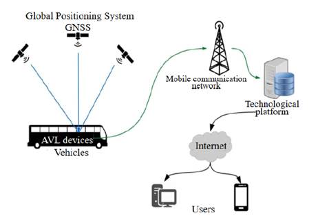
Figure 1: General architecture of an AVL application.
The term ‘low-orbit satellite’ groups all satellites that orbit the earth in a distance range between 500 and 1500 km. A short distance supposes an advantage for the development of the application, due to its decreased delays. However, these networks have some disadvantages, since each satellite has a smaller coverage area (footprint), which implies highly dynamic topologies [2].
Additionally, an LEO (Low Earth Orbit) satellite network is called a ‘constellation’. These constellations are usually distributed in circular orbital planes, where the satellites are placed evenly [3]. A polar orbit constellation is characterized by the inclination of its orbital planes, which is near 90°. An example of this is the Iridium network.
On the other hand, the constellations with an inclined orbit, also known as Walker constellations, are those that have orbital planes with an inclination of less than 90°, such as the Globalstar network [4].
Iridium network
This network is composed of 66 low-orbit cross-link satellites. The term ‘cross-link’ means that each satellite can communicate with any other satellite in the network, as well as with a terrestrial station named Gateway. This communication is possible even if the satellite has no direct communication with the Gateway [5].
Iridium offers a short-burst-data (SBD) service to transmit messages from a mobile terminal to a computer central. The SBD service is composed of a field application (FA), an Iridium subscriber unit (ISU), the Iridium satellite constellation, and the Gateway SBD subsystem (GSS), which connect through IP socket or email with the vendor application (VA) [6].
Materials and methods
The methodological design for the development of this research was divided into four phases, which are presented in Fig. 2.
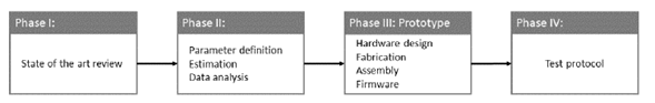
Figure 2: Development methodology.
In order to operate the system correctly, the AVL devices must be configured as described below:
-
When the mobile asset is within a cellular coverage area, the AVL device must send data through the network to the back-end server.
-
When the mobile asset is out of range, the AVL device must switch to satellite mode, sending the data to the backrest device through a serial port (usually RS232).
The operation criteria mentioned above imply a restriction related to the AVL device that supports the backrest system. The AVL device must allow the configuration described above. Some commercial devices that do this are Syrus, TT8750, and TT8750+, among others.
The length of the SBD messages is 10 bytes. For that reason, the device must create a package with the same or less length. The processing block extracts basic information to create a message. The details of this are given in the processing block section [7].
General architecture
The developed backup device (FA) uses the Iridium SBD service. The FA sends the data received from the AVL device to the low-orbit Iridium satellite through a 9603N (ISU) modem, which is embedded into the FA. The data is received by the Iridium terrestrial station (GSS) and then sent to the technological platform (VA) through the internet. Fig. 3 shows the described process.

Figure 3: General architecture of the backrest system.
Hardware design
Fig. 4 shows the block diagram of the hardware. The communication lines of all the blocks, except for the power supply, are two-way.
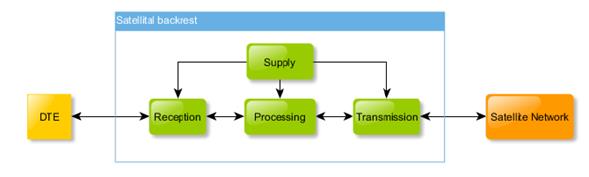
Figure 4: General architecture of the backrest system.
The DTE block is the system input and it corresponds to the AVL unit, which extracts the information from the mobile device to be sent to the satellite channel. The function of the reception module is to receive the information from the DTE and adjust the levels to send the data to the processing module. The processing block is responsible for system control. This block processes the information sent by the reception module and transmits it to the transmission module. The function of the transmission block is to adjust the processed information and send it to the satellite channel. Furthermore, the power module is transverse to the other modules, and its function is to provide the energy to the whole system. The energy supply is necessary for the proper functioning of the system.
Each block of the device was designed with the Altium Designer Software, one of the most powerful tools to design printed circuit boards.
Reception block
Its function is to receive the data from the AVL device and send it to the processing block. Its core is an RS232-TTL transceiver, which adjusts the voltage levels to avoid damage to the processing block. Fig. 5 presents the electronic circuit of this block.
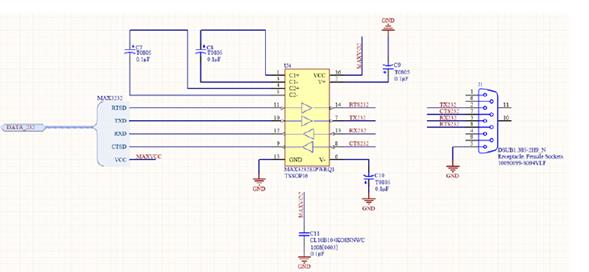
Figure 5: Reception block circuit.
Processing block
This block is the core of the device. It consists of a microprocessor, which receives the data from the reception block, extracts the most important information such as geographic coordinates, event code, velocity, and heading, and creates a package of 9 bytes. After the package is created, this block sends the package to the transmission block and returns an ACK to the AVL device if needed. Fig. 6 shows the electronic circuit of this block.
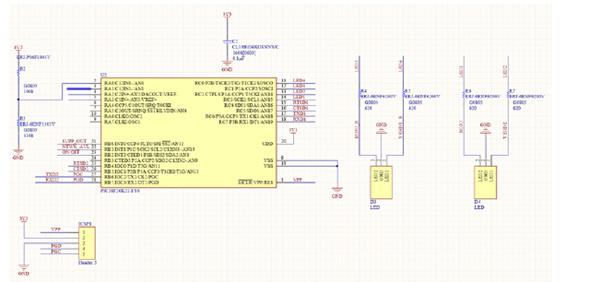
Figure 6: Processing block circuit.
Transmission block
The function of this module is to send the data package generated by the processing module to the satellite network. The input of these blocks is the TTL signal acquired through a UART port. These signals contain the message to be transmitted. The output is an RF signal in an L band with digital modulation. Fig. 7 presents a block diagram of this module.
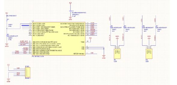
Figure 7: Transmission block circuit.
Supply block
This module supplies electrical energy to the whole system. Its design was based on the current demand of the device. Table I describes the current requirements.
Table I: Iridium antenna characteristics.
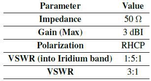
To satisfy the electrical demand, the circuit shown in Fig. 8 was designed. The circuit has two sources, one switching and other lineal [10].
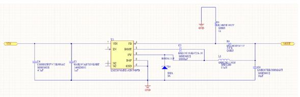
Figure 8: Supply block circuit.
Additionally, because the vehicle has an electrical environment with voltage peaks, among other issues, a protection circuit was designed to avoid damage to the device.
PCB design
Once the design of each block of the device was finished, the PCB design began. It was also designed with Altium Designer according to standard IPC 2221 [11]. Fig. 9 shows the final PCB.

Figure 9: Device PCB design.
Firmware design
The firmware controls all the logic of the device. It was written in C language with the CCS tool. Its logic is described in Fig. 10. The firmware receives the information from the AVL unit to validate it. Afterwards, in the validation process mentioned above, an information package is created which contains the most relevant data, such as message ID, geo-positioning coordinates, speed, and heading. Once the package contains the mentioned data, the information is sent to the transmission module and finally transferred to the satellite channel. Checking of satellites in line of sight is necessary before sending the information to the module. Otherwise, the system stores the information in the internal memory.

Figure 10: Firmware flow diagram.
Results
This electronic device allows data transference from the AVL device to a technology platform. It was assembled according to the IPC 2221 standard. Then, the electrical elements were tested to detect any failure (Fig. 11).

Figure 11: Developed electronic device.
Fig. 10 shows the final hardware. It was tested in a laboratory, following a hardware compliance test protocol, which registered, step by step, the standard IPC 2221 recommendations for the design, pre-assembly, and assembly of the power supply, microcontroller, display components and output radio frequency interface. Besides, it gives way to assess electrical functioning, the processing of online event information, and the emission of the appropriate antenna output power. The microcontroller was programmed using the developed firmware. This was done in order to carry out the operation test. To program the microcontroller, the following steps were followed:
-
An AVL Syrus device was connected to the equipment through the serial port.
-
An event was generated in the AVL device.
-
The light block of the backrest device confirmed the reception of the message.
-
The technological platform received the message and showed the correct position and event on the map.
Once the laboratory tests were successfully finished, the device was installed in a vehicle and tested in a real operation. For this purpose, an active was created in the Adminsat tracking platform, associated with the Syrus AVL and the satellite backup device. Using this platform, the vehicle was tracked for a week. Fig. 12 presents the report history generated by the platform.
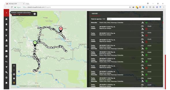
Figure 12: Tacking evidence, of the developed electronic device.
As shown in Fig. 12, the vehicle with the satellite device was not moving through cellular coverage areas. Specifically, the vehicle moved within the south Colombian area, and it worked correctly. The received information matches with the transmitted information, and the vehicle location reported by the AVL (latitude, longitude) unit corresponds to the reality.
It would have been desirable to compare the created device with other similar devices. However, this comparison was not possible because the Colombian manufacturers of equipment with AVL applications (DCT, Enfora, Skypatrol, Suntech, Teltonika, etc.) base their data transmissions in 100% cellular networks (2G) or 100% satellite networks, which would render it inequitable.
The AVL device does not allow sending data at rates of 9.600, 19.200, 8.400, 57.600, or 115.200 bauds from any of the Units (Syrus, TT8750, and TT8750+). This happens when the mobile is located inside tunnels or in areas with a high vegetation density. Another unfavorable condition was found during the transmission tests; researchers noticed that, when there was no line of sight, it was partially obstructed, or the satellite was not available in its orbit. This happens for antenna elevation angles between 5° and 175°, measured from the observation point and over the observation horizon. Unfortunately, for these scenarios, no information was received on the server.
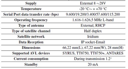
Table II describes the main technical specifications of the developed device.
Table II: Technical Specifications.
As a complement to this research, an economical study was performed. Currently, operators offer only message plans. This means that the user pays a monthly value for a limited quantity of messages, whose cost varies according to the plan. Considering the conditions when sending data, the commercial plan offered by Iridium is more convenient when a high volume of information is must be sent. Thus, 800 messages through the Globalstar network represent a cost equivalent to sending 1.200 messages through the Iridium network. As a conclusion, the proposed electronic device is a convenient technological solution for satellite backup of AVL units because of its low cost (53 USD), low power consumption (1,3 a maximumwhile active, and 15 mA on idle), small size (96,5_84,8_3,5 mm) and light weight (250 g). In addition, it does not require a subscriber identity module (SIM card).
Discussion
The device was able to communicate with other equipment such as the Syrus, TT8750, and TT8750+ AVLs at data transmission rates of 9.600, 19.200, 3.400, 57.600, and 115.200 bauds. The device correctly interprets the information related to the measurement variables and/or geolocation of mobile assets sent by AVL equipment. Additionally, it extracts the longitude, latitude, speed, heading, altitude, temperature, humidity, and code or identifier of the reporting event. It also configures the pattern, programs the commands, and sends the message to the technological platform. Previous functions are carried out by means of a satellite link with an effective isotropic radiated power: EIRP of 18 dBm +/- 2 dB.
Furthermore, the device correctly indicates its internal operation state to the user through LEDs, as well as allowing power inputs between 7 and 24 VDC. Information adjustment in the transmitter and its recuperation in the receptor was possible through communication protocols, implemented with different programming languages such as Java, Phyton, C, Django Framework, and Ajax web development techniques. Besides, for the mentioned development, environmentally friendly management of resources was carried out. Hence, electronic waste was reduced by reusing existing GPRS modems.
Mobile asset operation links at low microwave frequencies (L sub-band) with low earth orbit satellite networks (LEO) are justified by the power limitation in the terminal, a reduced latency (almost negligible of a few hundredths of a second), low losses (by atmospheric absorption and rain attenuation of the order of 0,0001). These conditions are presented for an electromagnetic wave with circular polarization to the right, at a frequency of 1611 GHz and a reduced coverage area (footprint), which implies highly dynamic typologies.
Additionally, it is important to remark that, for this project, the electronic device was designed according to the recommendations of IPC standard 2221. The use of this standard improves the design experience and guarantees correct electrical operation in the final product.
The electronic device can be improved as follows: the firmware can be optimized through the use of algorithms that allow sending more information in the same amount of bytes; and the security of the hardware can be improved, with additional protections to avoid damage due to overvoltage.
Conclusions
The information sent by the developed device corresponds to the data generated by the AVL device. This indicates that the processing of the information was correctly designed. Therefore, the block integration was also correct, and a functional device was thus obtained. The developed device is versatile;ts firmware was designed to receive future updates, which enhances its capacity and compatibility with other devices. Designing the device according to IPC standard 2221 improved the experience and guaranteed the correct electrical operation of the final product.
Acknowledgements
Acknowledgements
The authors thank the Escuela Colombiana de Ingeniería Julio Garavito for funding this study.
References
Licencia
Derechos de autor 2020 Hernán Paz Penagos, Néstor Rodrigo Guerrero Rodríguez

Esta obra está bajo una licencia internacional Creative Commons Atribución-NoComercial-CompartirIgual 4.0.
![]()
A partir de la edición del V23N3 del año 2018 hacia adelante, se cambia la Licencia Creative Commons “Atribución—No Comercial – Sin Obra Derivada” a la siguiente:
Atribución - No Comercial – Compartir igual: esta licencia permite a otros distribuir, remezclar, retocar, y crear a partir de tu obra de modo no comercial, siempre y cuando te den crédito y licencien sus nuevas creaciones bajo las mismas condiciones.

2.jpg)