DOI:
https://doi.org/10.14483/23448393.22038Published:
2025-08-01Issue:
Vol. 30 No. 2 (2025): May-AugustSection:
Civil and Environmental EngineeringThe Theoretical Analysis of the Use of Micropiles as Load-Recovering Elements via the Poulos and Davis Methodology
Análisis teórico del uso de micropilotes como recuperadores de carga a través de la metodología de Poulos y Davis
Keywords:
foundation, load, micropiles, settlements, strata (en).Keywords:
cimentación, carga, micropilotes, asentamientos, estratos (es).Downloads
References
R. Lorenzo, R. P. Cuna, E. Hernández, and W. Cobelo, “Aplicacion de la teoría de seguridad al diseño geotécnico de losas sobre pilotes,” Rev. Ing. Const., vol. 28, no. 3, pp. 251–265, Dec. 2013. http://dx.doi.org/10.4067/S0718-50732013000300003
V. Rama, “Pile foundations,” Geotech. Eng., vol. 1, no. 46, pp. 76–85, 2009.
J. Han and S. L. Ye, “A field study on the behavior of micropiles in clay under compression or tension,” Canad. Geotech. J., vol. 43, no. 1, pp. 19–29, Jan. 2006. https://doi.org/10.1139/t05-089
W. M. Castellanos Guerrero and E. Rodríguez Rincón, “Inclusión de micropilotes como elementos recuperadores de carga en cimentaciones: revisión del estado del conocimiento,” Ingeniería, vol. 27, no. 2, art. e16984, Apr. 2022. https://doi.org/10.14483/23448393.16984
Micropile design and construction reference manual, publication no. FHWA-NHI-05-039, US Department of Transportation, WA, USA, 2005.
A. S. A. Al-Gharbawi, M. Y. Fattah, and S. A. Abduhussain, “Behavior of soil reinforced with micropiles,” Open Eng., vol. 14, no. 1, art. 20220563, Jan. 2024. https://doi.org/10.1515/eng-2022-0563
A. S. A. Al-Gharbawi, A. M. Najemalden, and M. Y. Fattah, “Studying the behavior of expansive soil reinforced by micropiles,” Civil Eng. J., vol. 10, no. 1, pp. 265–279, Jan. 2024. https://doi.org/10.28991/CEJ-2024-010-01-017
A. Gutiérrez-Martín, J. P. Millán-Martín, R. Castedo, and J. I. Yenes, “Calculation of micropiles and anchors to reinforce a slope in emergency situations: application in Málaga, Spain,” Geomatics Nat. Hazards Risk, vol. 12, no. 1, pp. 716–740, 2021. https://doi.org/10.1080/19475705.2021.1887373
W. L. Chao et al., “Calculation model and numerical validation of horizontal capacity of micropiles with different section forms,” Adv. Civ. Eng., vol. 2022, art. 3709415, 2022. https://doi.org/10.1155/2022/3709415
K. Sternik and T. Blejarski, “Application of micropiles to the stabilization of a deflected old tenement house,” in 12th Int. Workshop Micropiles, 2014. [Online]. Available: https://www.researchgate.net/publication/263181280
C. J. Sainea Vargas, “Pile group analysis placed under seismic loading,” Rev. Fac. Ing. UPTC, vol. 20, no. 31, pp. 9–21, 2011. https://revistas.uptc.edu.co/index.php/ingenieria/article/view/1419
C. Mendoza, R. P. Da Cunha, M. Barbosa, and B. Caicedo, “Contribuciones para la rehabilitación de cimentaciones superficiales con pilotes auto-perforante en suelo tropical,” in From Fundamentals to Applications in Geotechnics, D. Manzanal and A. O. Sfriso, Eds. Amsterdam, Netherlands, IOS Press BV, 2015, pp. 1456–1463. doi: 10.3233/978-1-61499-603-3-1456
J. E. Alva Hurtado, Diseño de cimentaciones, 1st ed. Lima Peru: ICG, 2007.
A. F. Cordeiro, R. P. Cunha, M. M. Sales, P. Kuklik, and Broucek M., “Influence of interaction factors and defective piles on piled raft behaviour,” in Foundations: Proceedings of the Second BGA International Conference on Foundations, M. J. Brown, M. F. Bransby, A. J. Brennan, and J. A. Knappett, Eds. Scotland, UK: Taylor & Francis, 2008, ch. 38, pp. 476–484.
A. F. Cordeiro, R. P. Cunha, M. Broucek, and M. M. Sales, “Piled rafts with defective piles: Influence of reinforcement systems,” in Foundations: Proceedings of the Second BGA International Conference on Foundations, M. J. Brown, M. F. Bransby, A. J. Brennan, and J. A. Knappett, Eds. Scotland, UK: Taylor & Francis, 2008, pp. 486–492.
R. Pinto da Cunha and A. F. Cordeiro, “Comportamento pós-reforço de grupos de fundação com uma única estaca defeituosa,” in XV Jor. Geotéc. Ing. Colomb., pp. 113–118.
Y. C. Tan, C. M. Chow, and S. S. Gue, “Piled raft with different pile length for medium-rise buildings on very soft clay,” in 16th Int. Conf. Soil Mech. Geo. Eng., Osaka, 2005, pp. 2045–2048, doi:10.3233/978-1-61499-656-9-2045
I. Y. Salena, “A case study of foundation failure in the existing residential building,” Jurnal Teknik Sipil Fakultas Teknik, vol. 4, no. 2, pp. 91–103, 2016. https://doi.org/https://doi.org/10.35308/jts-utu.v2i1.340
B. M. Das, Fundamentos de ingeniería de cimentaciones, 2nd ed. Ciudad de México, Mexico: Ed. Thompson, 2011.
H. G. Poulos and E. H. Davis, “Settlement of pile groups,” in Pile Fundation Analysis and Design. Hoboken, NJ, USA: Wiley, 1980, pp. 109-141.
A. Fuentes, “Confección de la propuesta de norma de diseño geotécnico de cimentaciones sobre pilotes,” MS thesis, Univ. Cen. Villas, Santa Clara, Cuba, 2008. https://doi.org/10.13140/RG.2.2.28272.61440
K. Terzaghi and R. B. Peck, Soil mechanics in engineering practice, 2nd ed. New York, NY, USA: Wiley International, 1967.
V. H. Fernandes Bonan, A. Sampaio Moura, and G. R. Ayala Llanque, “Experimental study of the group effect of short piles excavated in a granular soil profile,” Ingeniare, vol. 28, no. 2, pp. 323–334, Jun. 2020. https://doi.org/10.4067/S0718-33052020000200323
H. G. Poulos, “Analysis of the settlement of pile groups,” Geotechnique, vol. 18, no. 4, pp. 449–471, 1968. https://doi.org/10.1680/geot.1968.18.4.449
H. G. Poulos and N. S. Mattes, “Settement and load distribution analysis of pile groups,” Aust. Geom. J., vol. 1, no. 1, pp. 18–28, 1971.
E. Rodriguez, “Análise experimental do comportamento de sistemas radier estaqueado em solos moles em processos de adensamento,” Doctoral thesis, Dep. Eng. Civ., Univ. Brasília, Brasília, Brazil, 2016.
E. Rodríguez and C. Rincón, “Modelación física en centrífuga, de un muro pantalla sin anclaje en una arcilla blanda,” MS thesis, Dep. Ing. Civ. Amb., Univ. Andes, Bogota, Colombia, 2001.
R. B. Peck, W. E. Hanson, and T. H. Thornburn, Foundation engineering, 2nd. ed. New York, NY, USA: Wiley, 1974.
T. Whitaker, “Experiments with model piles in groups,” Géotechnique, vol. 7, no. 4, pp. 147–167, 1957. https://doi.org/10.1680/geot.1957.7.4.147
E. Rodríguez Rincón, R. P. da Cunha, and B. Caicedo Hormaza, “Analysis of settlements in piled raft systems founded in soft soil under consolidation process,” Canad. Geotech. J., vol. 57, no. 4, pp. 537–548, 2020. https://doi.org/10.1139/cgj-2018-0702
A. Mandolini, R. Di Laora, and Y. Mascarucci, “Rational design of piled raft,” in Proc. Eng., vol. 57, pp. 45–52. doi: 10.1016/j.proeng.2013.04.008
L. de Sanctis, A. Mandolini, G. Russo, and C. Viggiani, “Some remarks on the optimum design of piled rafts,” in Deep Foundations 2002: An International Perspective on Theory, Design, Construction, and Performance, M. W. O’Neil and F. C. Townsend, Eds. Orlando, Florida, USA: American Society of Civil Engineers (ASCE),c2002, pp. 405–425. https://doi.org/10.1061/40601(256)30
E. Rodríguez Rincon, B. Caicedo Hormaza, and J. F. Rodríguez Rebolledo, “Comparative analysis of Piled Raft Foundation System (PRFS) settlements placed on soft soils via geotechnical centrifuge,” Soils Rocks, vol. 44, no. 2, art. 062321, Apr. 2021. https://doi.org/10.28927/SR.2021.062321
M. Delgado Vargas, Ingeniería de fundaciones. Fundamentos e introducción al análisis geotécnico, 2nd ed. Bogotá, Colombia: Alfaomega, 2000.
How to Cite
APA
ACM
ACS
ABNT
Chicago
Harvard
IEEE
MLA
Turabian
Vancouver
Download Citation
Recibido: 4 de agosto de 2024; Aceptado: 16 de abril de 2025
Abstract
Context:
Micropiles have been mainly employed as soil reinforcement or supporting elements. As load-recovering elements, they have been used in pile groups where oneoftheelements hasturnedouttobedefective or incomplete. This type of use has not been directly reported in the literature, so it is important to generate knowledge about the conditions to be considered when evaluating the use of micropiles as replacements for defective piles.
Method:
This research verified and described the settlement behavior and load distribution of both piles and micropiles for five proposed models. The results were obtained through the analytical methodology by Poulos and Davis for pile group settlement, analyzing the influence of three variables on micropiles: position in the cap area, spacing, and quantity.
Results:
The load distribution in the micropiles showed greater uniformity as their number increased. Likewise, a load increase was observed as the distance between the micropiles and the upper left corner of the cap decreased. With greater spacing and micropile count, the settlements decreased.Conclusions: In order to use micropiles as load-recovering elements in existing foundations, it is convenient to consider variables such as quantity, position, and spacing, as they influence both the load distribution and the settlements of the structure.
Keywords:
foundation, load, micropiles, settlements, strata.Resumen
Contexto:
Los micropilotes han sido empleados principalmente como elementos de refuerzo del suelo o de apoyo. Comorecuperadores de carga, se han utilizado en grupos de pilotes donde uno de los elementos resulta defectuoso o incompleto. Este tipo de uso no se ha reportado de manera directa en la literatura, por lo que es importante generar conocimiento sobre las condiciones de análisis que deben ser consideradas al evaluar el uso de micropilotes para reemplazar pilotes defectuosos.
Método:
En esta investigación se verificó y describió el comportamiento en asentamientos y la distribución de carga de pilotes y micropilotes en cinco modelos propuestos. Los resultados se obtuvieron por medio de la metodología analítica de Poulos y Davis para el asentamiento en grupos de pilotes, analizando la influencia de tres variables en los micropilotes: la posición en el área del cabezal, la separación y la cantidad.
Resultados:
La distribución de carga en los micropilotes presentó mayor uniformidad a medida que estos aumentaban en número. Asimismo, se observó un aumento de la carga conforme se reducía la distancia entre los micropilotes y la esquina superior izquierda del cabezal. Con una mayor separación y una mayor cantidad de micropilotes, los asentamientos disminuyeron.
Conclusiones:
Para utilizar micropilotes como recuperadores de carga en cimentaciones existentes, es conveniente tener en cuenta variables como la cantidad, la posición y la separación, pues inciden tanto en la distribución de carga como en los asentamientos de la estructura.
Palabras clave:
cimentación, carga, micropilotes, asentamientos, estratos..Introduction
When constructing a structure, the design of its foundation system is decisive, as it is responsible for transmitting and distributing the loads of the construction to the soil layer. In this process, two conditions must be analyzed, i.e., the bearing capacity (ultimate state) and the settlements (service state) 1, in order to ensure functionality throughout the structure’s useful life. Pile-type foundations (deep foundations) are used when shallow foundations are not feasible. This is a construction solution that dates back to stilt houses and is common in ports or cities, where prefabricated wood has also been used as foundation material since the upper soil strata have deficient bearing capacities. It has been demonstrated that, during the construction or service life of deep foundations, conventional piles can exhibit failures such as pile shaft cracking, concrete contamination, and pile heading. Meanwhile, in non-conventional alternatives such as wood piles, the material deteriorates due to interaction with the soil 2. These issues may affect both the bearing capacity and the settlements of foundations, making it necessary to take corrective measures to repair and ensure the functionality of these structures. Amongthe measures referenced in the literature for the structural recovery of foundations is the use of micropiles 3.
Oneofthemainobjectives of the use of micropiles has been to serve as an element for load recovery, especially in shallow foundations. Micropiles have been used as soil reinforcement or underpinnings, as proven andanalyzedbyseveral authors. In Colombia, this technique has been limited to the expertise of the assigned geotechnical engineer, who combines empirical knowledge and successful experiences 4).
This paper analyzes the behavior of foundation systems consisting of pile groups in which micropiles have been used to replace items that have lost their functionality. This analysis focuses on both the settlements and the load distribution of the groups’ constituent elements, as a function of variables such as position, spacing, and micropile count. In order to meet the objectives of this work, we employed a model that considers a group of piles with one defective element that is replaced by two, three, four, or five micropiles, positioned symmetrically with respect to the axis of the replaced pile, as well as arranged in different geometries.
Theoretical framework
State of the art
Amicropile is a small-diameter (typically less than 300 mm), drilled, and grouted non-displacement pile that is typically reinforced. A micropile is constructed by drilling a borehole, placing steel reinforcement, and grouting the hole. Micropiles can withstand relatively significant axial loads and moderate lateral loads and may be considered a substitute for conventional driven piles or drilled shafts, or as one component in a composite soil/pile mass 5.
Micropiles are used to reinforce soil strata with low bearing capacities such as soft clays, which often generate excessive settlements. In 6, three types of micropiles were evaluated as reinforcements for a soft clay stratum. These micropiles had lengths of 60, 120, and 180 mm. With proper arrangement, the 60 mm micropiles increased the bearing capacity of a rigid steel footing by 40-60%. The 120 mm micropiles achieved an increase of 45-65%, while the 180 mm micropiles improved the bearing capacity by 55-65%. These results show the feasibility of using micropiles as reinforcements, favorably stabilizing and increasing the bearing capacity of the soil.
7 analyzed the behavior of expansive soils when reinforced with micropile groups, aiming to improve their bearing capacity. Three types of micropiles of different lengths (1B, 2B, and 3B) and two width configurations under the footing (1B and 2B) were used in the study. The results showed significant increases in the bearing capacity of the soil. For example, by using micropiles of length 1B with a 2Bconfiguration under the footing, an increase in bearing capacity from 35 to 55% was achieved. However, by increasing the length of the micropiles from 1B to 2B, only an additional 7% was obtained. This highlights the feasibility of using micropiles to reinforce foundations in expansive soils, offering an effective solution for stabilizing the soil and improving its bearing capacity.
Micropiles have been effectively used to improve the stability of slopes affected by landslides. A representative case is a study carried out in Málaga, Spain 8, where a 40-year-old embankment suffered landslides due to torrential rains. In response, an emergency plan was implemented to stabilize the slope and prevent further damage to nearby buildings. The solution consisted of installing a row of micropiles anchored to the resistant rock stratum, using two different lengths (21 and 25 m) adapted to the morphology of the geotechnical strata. The design was elaborated using the SLIDE V5 software, and the results showed that micropiles, when combined with passive anchors, can significantly improve slope stability. In addition, it was observed that the factor of safety increases with micropile length, although it tends to stabilize above a critical value.
9 conducted a study on the use of micropiles as slope stabilizers, with the objective of developing a theoretical model to calculate the horizontal bearing capacity of different micropile types. Among the cross-sections analyzed for these elements were single steel bars, multiple steel bars, and tubes. This study included numerical simulations for two common conditions (soil-soil and soil-rock), with the purpose of analyzing the deformation of the slope reinforced with micropiles, as well as the failure regulation. The results highlighted that the bending capacity of micropiles is a critical element that should be carefully considered when using them as slope reinforcement. Furthermore, the developed model was considered optimal for the rapid design of micropiles to support slope restraint systems, especially in emergency situations.
Micropiles have been used in several investigations to increase the bearing capacity and reduce settlement, particularly in existing shallow foundations 10) (11. Very few studies have focused on analyzing their inclusion in the recovery of deep foundations.
In the Federal District of Brazil, a study using micropiles to recover the bearing capacity of footings carried out load tests on different piled raft foundation models, with and without footing contribution. The results indicated that the raft provides approximately 23% of the system’s bearing capacity. Therefore, considering the use of micropiles is recommended when designing rehabilitation systems for foundations 12. However, there is a great disadvantage: the limited number of academic studies on this type of micropiles when used for rehabilitating shallow foundations with problems; the contribution of each element in the pile raft system is unknown, which constitutes a source of uncertainty during the implementation of this solution 4.
As for pile groups, the settlement of an individual pile under working load is often so small that it poses no issue and is negligible. However, the combined effect of these piles can produce considerable settlements 13.
The literature on pile groups has analyzed the way in which an imperfection in one of the piles can affect the structural capacity of the system. An outstanding case is the work carried out by 14, who studied a group of piles configured in a 2 x 2 matrix with similar geometrical characteristics and a symmetrical distribution in a slope. In this study, it was identified that one of the piles had a structural imperfection, including a reduced length, which significantly affected the behavior of the system. Based on this condition, the researchers analyzed the settlements and load distribution of the piles, comparing the results against the initial conditions of a fully functional pile raft system. This study considered that the ballast comes into contact with the bearing layer of the soil, generating differential settlements across its area. The results showed an increase in settlements in the area adjacent to the defective pile, due to a decrease in its structural capacity and length. Regarding the load distribution, the two piles located at an equal distance from the defective pile showed a proportional increase in their load, in contrast to the initial conditions of the system. Moreover, on the other side, the farthest pile exhibited a decrease in its working load. This analysis underscores the importance of performing rigorous evaluations to determine the pile damage level. Such evaluations are fundamental to developing strategies that ensure the functionality and safety of a structure, preventing the damage caused by a compromised element.
15 carried out a study on a pile raft system composed of a 2 x 2 pile group with identical geometric characteristics. This analysis considered the use of uniform piles as reinforcement elements when defective piles were identified. The study covered five cases: the first two evaluated the inclusion of one reinforcement pile, while the remaining three considered the addition of two piles at different positions within the raft. By implementing reinforcement piles, the area of the raft increased, adopting a rectangular geometric shape. The GARP4 and DEFPIG programs were used to model different scenarios, and the results indicated that, in most cases, it is essential to include at least one additional pile. However, the location of the reinforcement pile plays a crucial role in the load distribution of the foundation piles. Therefore, careful planning is necessary to avoid exceeding the load-carrying capacity of the piles and ensure an optimum safety factor for the foundation. It was also observed that piled systems offer a better load distribution compared to free-head foundations. In particular, cases 1 and 2 showed the best load distribution, even when a single reinforcement pile was used.
16 investigated the post-reinforcement behavior of a pile raft with one defective pile. To this effect, they carried out a numerical analysis that considered the inclusion of a reinforcement pile in different positions within the raft area. They identified key points to be taken into account in these particular situations, specifically when it comes to load distribution under reinforced conditions. The inclusion of a reinforcement pile near the damaged element significantly improved the overall factor of safety. However, when using piles other than the original ones, it is crucial to keep the center of gravity of the block intact to ensure optimal results regarding the working load of the foundation-bearing elements. Reinforcement inevitably leads to a redistribution of loads. For some piles, this may imply an increase in load, whereas, for others, it may result in a decrease. This behavior is influenced by factors such as the position of the reinforcement, the geometry of the raft, and the type of reinforcement pile used.
Differential settlements are usual in flexible pile groups. However, increasing the number of piles counteracts this phenomenon. If the piles are distributed over the entire section under the head or raft, the differential settlements can be reduced by up to 60% 17. It is important to bear in mind that the length of the piles determines their stiffness or flexibility, as a result of variations in the relative soil-pile stiffness 11).
Areference study on the use of micropiles to recover the bearing capacity of an existing foundation took place in Maryland, where micropiles were used to rehabilitate a foundation system composed of timber piles, which, due to their exposure to water, had lost their bearing capacity. This was done for a 75-year-old bridge on the Pocomoke River 5).
Another study was conducted in a residential unit composed of 88 houses in Taman Tunas Muda (Sungai Ara, Penang, Malaysia), which was located on a clay/loamy soil stratum with a low bearing capacity. The houses exhibited settlements of such magnitude that they caused structural damage. The corrective actions applied to solve this problem included the use of micropiles and beams to shore up the foundation, which comprised groups of reinforced concrete piles. As a final result, the movement of the houses was stabilized, demonstrating the viability of micropiles in settlement control 18.
Based on the existing literature on the subject, this research aims to understand the behavior of micropiles when used for load recovery and settlement control, aiming to advance towards a more rigorous and detailed numerical modeling of pile groups that include these elements. This should allow analyzing the effect of soil-structure interaction and other variables on the behavior of pile group foundations with bearing elements of different geometries.
Model used to determine settlement and load distribution in pile groups
Bearing capacity of the piles
The bearing capacity of a pile is equivalent to the sum of the per-shaft and per-tip bearing capacities, without taking into account the pile’s own weight 19. Poulos proposed Eq. (1) to obtain the ultimate capacity of a pile 20.

where λ is the dimensionless coefficient of frictional capacity, a function of the penetration depth of the pile into the soil;  , is the average effective stress between the soil surface and the pile tip; c
m
, is the average cohesion along the pile; N
c
, is the bearing capacity factor; and A
s
and A
b
are the surface and base areas, respectively.
, is the average effective stress between the soil surface and the pile tip; c
m
, is the average cohesion along the pile; N
c
, is the bearing capacity factor; and A
s
and A
b
are the surface and base areas, respectively.
Bearing capacity of pile groups
The bearing capacity of a pile group depends on the working mode of the element that transmits the load to the pile head. This is called free head if the cap is not in contact with the bearing soil layer, or pile foundation if it is 20.
The concept of efficiency is understood as the ratio between the ultimate capacity of the group and the sum of the individual capacities of the piles that make up a group 21, which can be determined through some theoretical approaches, as shown in Table I.
Table I: Pile group efficiency
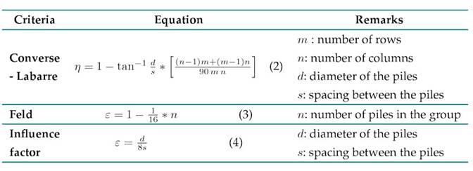
According to 20, there are two types of pile group rupture behavior:
-
Rupture as a failure block equivalent to the group. 22) proposed Eq. (5) for calculating the ultimate bearing capacity of pile groups in cohesive undrained soil strata

where B r is the width of the group; L r is the length of the group; c is the undrained cohesion at the base of the group; N c is the bearing capacity factor at a depth L; L is the length of the piles; and c¯is the average cohesion between the surface and a depth L.
Rupture as a transition between individual or block failure. 20 evaluated the load capacity transition between block and individual failure. They expressed this relationship using Eq. (6).
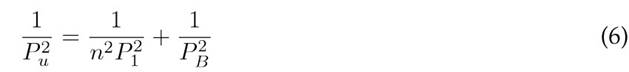
where P 1 is the ultimate bearing capacity of a pile, and P B is the bearing capacity of the group in block failure.
Settlement of individual piles
To calculate the settlement at the head of a pile, 20 evaluated an incompressible pile in a finite half-space, proposing Eq. (7) to determine the unit settlement of floating piles
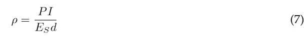
where P is the load on the pile, E S is the average modulus of elasticity of the soil, and I is the influence factor for settlement, which is calculated using Eq. (8).

where I o is the influence factor for an incompressible pile supported in a semi-infinite space with a Poisson ratio of 0.5; R k is the correction factor for the compressibility of the pile; R h is the correction factor for finite depth of the stratum where the base is supported; and R v is the correction factor for Poisson’s ratio. (20) constructed a series of abacuses to obtain these influence and correction factors as a function of dimensionless pile parameters such as the slenderness ratio (L/d), the relative stiffness (K), the shaft-base diameter ratio, and the Poisson ratio of the bearing soil stratum.
Settlement in pile groups
The group effect influences both settlement calculations and pile group capacity 23,24 and 25 proposed a methodology for calculating the settlement of a pile group, which is characterized by the inclusion of a term called the interaction factor (α).. This term allows calculating the settlement of a pile while considering the influence of adjacent piles, as defined in Eq. (9).

25 also devised a methodology to calculate the interaction factors as a function of dimensionless pile spacing (s/d), L/d, and K. This methodology is based on the analysis of two similar piles in terms of geometry and working load. 20 extended this analysis to groups of piles with different geometric characteristics, defining the settlement for a pile in a group with this particularity. This is shown in Eq. (10).

where ρ 1f is the unit settlement for pile j,P is the working load of pile j, and α kj is the interaction factor for the spacing between piles k and j, with the geometric parameters of pile j.
To mathematically solve the settlement equations, (20) included the vertical load equilibrium, as expressed in Eq. (11).
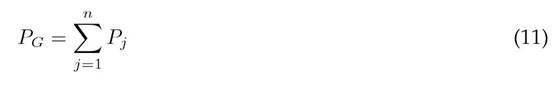
where P G is the total group load.
This method imposes two boundary conditions to calculate the settlement and working load of the piles within the group. The first one considers a uniform load distribution in all piles in order to represent a flexible cap, and the second considers equal settlements in the piles, representing a rigid cap 20).
Methodology
This research evaluated the behavior of pile groups in which a pile-type bearing element had been replaced with micropiles due to failures arising from both construction and service. To this effect, the following methodology was employed:
-
Determination of the pile group base model
-
Determination of the micropile configurations to be evaluated
-
Description of the foundation soil
-
Determination of the bearing capacity of an individual pile and of the pile group (considering the efficiency)
-
Determination of the settlement of a pile and a micropile
-
Application of the influence factor methodology (Poulos and Davis method) to determine the load on the bearing elements and the settlement of the proposed groups (this procedure did not consider the failed pile)
Pile group base model
The materials and models used in this research are based on a study carried out in a geotechnical centrifuge of pile groups with various spacings 26). This reference work also delimited the type of soil to be studied, as described in this section.
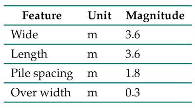
The base model of this research was composed of a 2 x 2 pile array whose spacing was equivalent to three times their diameter (Fig. 1).
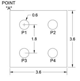
Figure 1: Dimensions in meters (m) for the initial research model
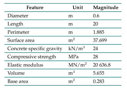
In this model, the piles had similar geometric characteristics, which are described in Table II. Pile 1 was considered defective and replaced with several micropile arrays. The methodology proposed by Poulos and Davis was used to evaluate the loading variables of the piles and micropiles, as well as their settlement.
Table II: Pile properties
Pile and micropile group models
Several models consisting of piles, micropiles, and a rigid cap that was not in contact with the ground surface (free head) were proposed. Within each model, some configurations were evaluated, establishing specific positions for the micropiles within the cap area, so that they remained symmetrical about the axis of the pile to be replaced. In addition, each configuration evaluated three micropile spacings with respect to the axis of the defective pile, i.e., 2.5, 3, and 3.5 times their diameter. Tables II, III, and IV present the properties of piles, micropiles, and head considered in this research.
Table III: Micropile properties
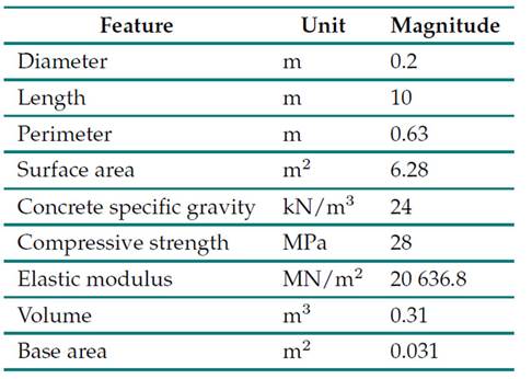
Table IV: Cap properties
The models proposed for study, with their corresponding configurations, are the following:
-
Three piles- two micropiles (3P-2M): four configurations (Fig. 2)
-
Three piles- three micropiles (3P-3M): two configurations (Fig. 3)
-
Three piles- four micropiles (3P-4M): two configurations (Fig. 4)
-
Three piles- five micropiles (3P-5M): three configurations (Fig. 5)

Figure 2: Micropile positioning for the 3P-2M model configurations
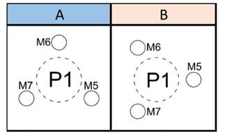
Figure 3: Micropile positioning for the 3P-3M model configurations
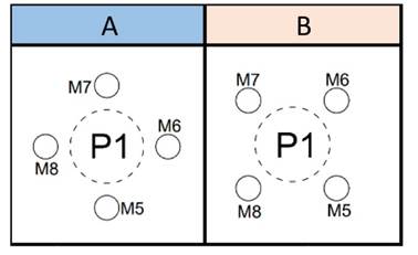
Figure 4: Micropile positioning for the 3P-3M model configurations
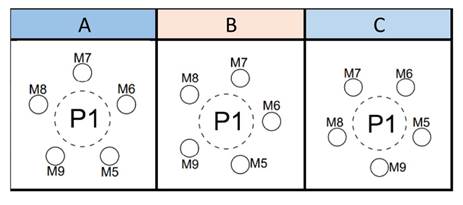
Figure 5: Micropile positioning for the 3P-3M model configurations
Soil bearing stratum
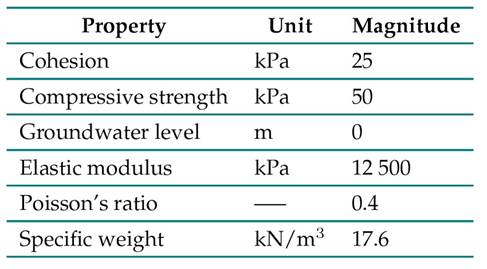
This research considered a soft clay soil profile with mechanical characteristics that resemble the clays present in the city of Bogotá (Colombia), as presented in previous research 26) (27Its cohesion ranges between 10 kN/m2 at the surface and 40 kN/m2 at depth. By means of these soil properties, and through correlations established in other works 19) (28, the parameters presented in Table V were obtained.
Source: adapted from 26
Table V: Soil bearing stratum properties
Load capacity
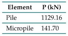
By means of Eq. (1) (20), the load capacity of a pile with the characteristics described in Table II can be calculated, as well as that of a micropile exhibiting the parameters in Table III, assuming that these elements are located within a layer of undrained clay (described in Table V). This yields the results presented in Table VI.
Table VI: Load capacity of the piles and micropiles
To calculate the load distribution of the 2 x 2 pile arrangement (Fig. 1), a free-headed foundation was considered. Therefore, the load on the four bearing elements (with similar geometric characteristics) was the same 20. To determine the load capacity of the base model, Eqs. (5) (22) and 6 (20) were considered, as well as an evaluation using the three theoretical approaches shown in Table I. All these calculations were based on the load capacity obtained for the pile type described in Table VI. The results presented in Table VII were obtained.
Table VII: Load capacity of a 2 x 2 group of piles with similar geometric characteristics
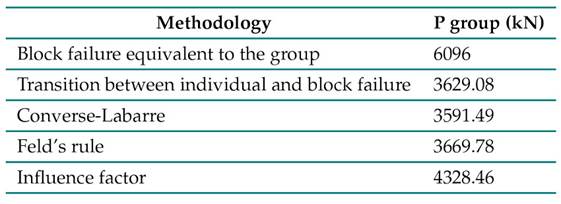
Based on the results in Table VII, the load capacity of the base model was 3591.49 kN, i.e., the lowest value found by the different methodologies under study. To calculate the settlement, a working load of 1796 kN wasconsidered, ensuring a safety factor of 2.
Settlements
To calculate the settlement of pile groups, it is necessary to obtain the unit settlement for the load-bearing elements in the model. By applying Eq. (8), proposed by Poulos and Davis for the settlement of a floating pile in a homogeneous soil mass, and taking the dimensionless pile and micropile parameters in Table VIII into account, the influence and correction factors for the elements in Table IX (whose geometric characteristics are described in Table II and III) were obtained.
Table VIII: Dimensionless parameters for the piles and micropiles
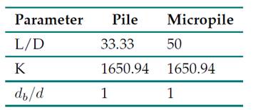
Table IX: Influence and correction factors for the piles and micropiles
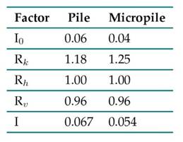
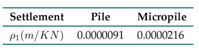
Asmentionedabove,theunit settlement for the piles and micropiles was obtained using Eq. (8). The results are presented in Table X.
Table X: Unit settlement for the piles and micropiles
Applying the Poulos and Davis method in calculating the load distribution and settlement of pile groups with different geometries
To apply the method proposed by Poulos and Davis, it was assumed that all the studied groups exhibited a rigid head. Therefore, all the piles and micropiles had the same settlement but a different working load. Based on this condition, and using Eq. (10) (20), expressions for calculating the settlement of each element in the different models and configurations were proposed. Thus, in a group with six elements (excluding the pile to be replaced), an equal number of equations for settlement calculation was obtained.
To solve these systems of equations, Poulos and Davis introduced Eq. 11) (20, which describes the vertical load equilibrium. Starting from the boundary condition used in this research (i.e., the rigid cap), this expression was formulated while considering a total load of 1796 kN for all the groups of piles and micropiles. Thus, an additional load balance equation was obtained for each group, which allowed solving the systems of equations and determining the working load of each bearing element, as well as the overall settlement of the analyzed groups.
Results
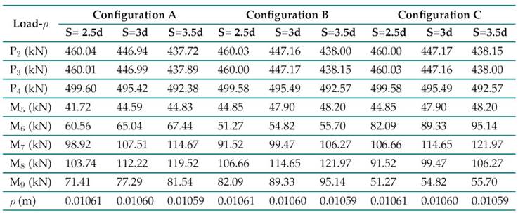
Tables XI, XII, XIII, and XIV present the results obtained for the working load of the piles (P) and micropiles (M) in kN. Also shown are the settlements for each model and configuration, expressed in m, considering the increase in the spacing (S) between the micropiles, with values equivalent to 2.5, 3, and 3.5 times their diameter (d). These results were obtained by applying the method proposed by Poulos and Davis for the settlement in groups of piles with elements of different geometries.
Table XI: Load-settlement results for the 3P-2M model
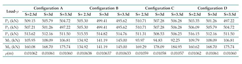
Table XII: Load-settlement results for the 3P-3M model
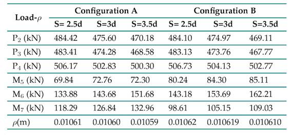
Table XIII: Load-settlement results for the 3P-4M model
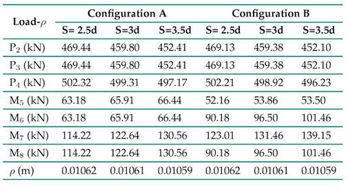
Table XIV: Load-settlement results for the 3P-4M model
Based on the above, the following can be stated:
-
The micropiles close to the edge of the head generate higher loads. This particularity has been documented in previous studies involving groups of rectangular piles with a rigid cap —here, the edge piles bear a greater load than those at the center 29).
-
The working load of the piles decreases as the spacing of the micropiles increases, with the latter assuming a greater proportion of the load. There is a 4-7 % increase for the 3P- 2M model.
-
In micropile-type elements that are symmetrical about the system’s load center, there is an equal distribution of the working load.
-
Increments in micropile spacing influence the settlement value: as the former increases, the latter tends to decrease. In this case, when the spacing exceeds 2.5d, the settlement is reduced in all models. This behavior resembles that of a pile raft system in that the settlements are reduced in proportion to the distribution of the pile-like elements under the cap 30.
Note that the average spacing of a pile is defined using Eq. (12).
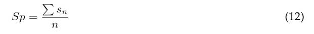
where s n , a variable parameter, is the separation between the center of a pile and the center of a micropile; and n is the number of micropiles in the model. If the magnitude of Sp is equal among the elements of the group, the working load will have an equal magnitude.
Discussion
The results obtained were analyzed by examining the behavior of the piles (P) and micropiles (M) in terms of their working load. This analysis also considered the settlement of the foundations proposed for each case.
Settlement
To analyze the settlement of the proposed models, the form factor (FF) was used, a parameter that allows characterizing the behavior of pile raft systems and has been associated by researchers with the load distribution and settlement of the elements within a system. The FF, which accounts for the geometric characteristics of both the cap and the pile group 31, is expressed in Eq. (13).
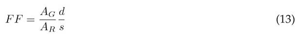
where A G is the area formed by the pile group, A R denotes the area of the cap, s represents the pile spacing, and d is the pile diameter.
In this research, the settlements of the proposed models were evaluated by means of a modified form factor (FF’), which was calculated based on the geometric characteristics of the groups formed only by micropiles, as shown in Eq. (14).
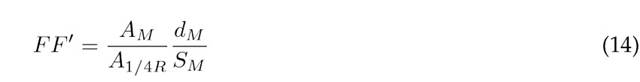
where A M denotes the area formed by the group of micropiles. To calculate A M , the expressions presented in Table XV were considered for each specific model, given that no common geometric pattern was observed in all models as the number of micropiles increased. Note that A 1/4R is equivalent to 1/4 of the area of the initial model (Fig. 1), d M denotes the micropile diameter, and S M denotes the spacing between the micropiles.
Table XV: Expressions for calculating A
M
in the models under study
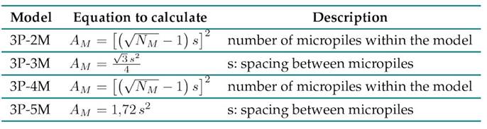
The mathematical expressions used to calculate the area of the micropiles group (A M ) in the 3P-3M and 3P-5M models correspond to formulas for calculating the area of an equilateral triangle and a pentagon, respectively. For the 3P-2M and 3P-4M models, we decided to use an expression established by 32 regarding the optimal design of plate-pile foundations with pile groups of square geometry.
Fig. 6 shows the average settlements obtained for each model as the micropile spacing increases. These are presented with respect to the FF’.
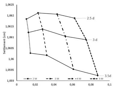
Figure 6: Average settlements obtained for the analyzed models
These values suggest a more effective settlement control arising from two conditions: increases in micropile spacing and count. However, note that, for a spacing of 2.5d, despite the increasing number of micropiles, the average settlement increases in models with three and four structural elements of this type.
Among the models and their configurations, a 3.5d spacing with respect to the pile to be replaced yields the greatest settlement reduction. A similar behavior regarding settlement control was observed among rigid cap pile groups with pile raft systems, as documented in several works: the settlement of pile raft systems can be reduced by increasing pile spacing, given that it improves their distribution over the raft area 30.
A more effective settlement control is achieved with five micropiles in the foundation structure —in this work, this corresponds to the three configurations of the 3P-5M model (Fig. 6). Previous studies have shown that, when the FF increases, settlement reduction in pile raft systems becomes more significant 33. In this research, the FF’ was considered for settlement analysis, and the results indicated that an increase in this regard contributes to better settlement control in the studied models.
Load on the piles
In the studied models, a change in the load (Q) supported by the piles was observed with respect to the initial model (Fig. 1), with similar geometry and a rigid cap. The element with the largest load increase was P 4. The load selected for the initial model ensured a safety factor of 2 with respect to the ultimate capacity of the pile group, but, after replacing P 1 with micropiles, this factor decreased below 1.75 in groups with two micropiles. Fig. 7 compares the working load behavior of P 4 and P 2 after introducing micropiles and increasing their number and spacing. The results indicate that the load on P 4 tends to decrease as the micropile spacing and count increase, which increases its safety factor.
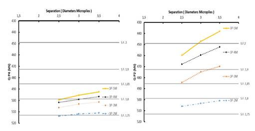
Figure 7: Load variations in P2 and P4 as a function of micropile count and spacing
In 3P-5M, evaluated with a spacing of 3.5d, P 2 and P 4 exhibited the highest safety factors (over 2 and 1.8). Thus, a relationship could be established between the safety factor of the piles and the settlement of the studied models: the latter tends to decrease as the former increases. Moreover, as the micropile spacing and count varies, P 2 exhibits a greater reduction in working load than P 4. This element reported the highest safety factor among all elements and models.
Fig. 7 shows that the most considerable change in the working load of P2 and P4 occurs when going from two to three micropiles. This effect could be related to a more uniform load distribution, as the 3P-2M model exhibited the greatest load difference.
Load on the micropiles
The results obtained for the working load of the micropiles indicate a direct relationship between the distance from the center of the structural element to point A on the head (Fig. 1). Fig. 8 presents a comparison of the load-distance relationship at point A for the micropiles in 3P-2M and 3P-3M. Likewise, Fig. 9 compares this relationship for 3P-4M and 3P-5M.
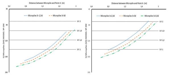
Figure 8: Micropile loads for models 3P-2M and 3P-3M, as a function of their distance to point A in the cap
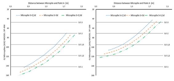
Figure 9: Micropile loads for models 3P-4M and 3P-5M, as a function of their distance to point A in the cap
In general, the working load of the micropiles increases as their distance to point A (i.e., the corner) is reduced. In groups of piles with a rigid cap, it has been established that the elements positioned at the edge tend to support higher loads. This could be explained by the distribution of pressures along the rigid cap 34. A particular behavior was observed in all models when considering a distance to point A greater than 1.5 m and a spacing of 2.5d. When the spacing increased from 2.5d to 3d, so did the load, but, when the spacing increased to 3.5d, this value tended to decrease.
An evaluation of the ultimate condition based on the results shown in Fig. 8 and Fig. 9 indicated that, in 3P-2M, micropiles with a distance to point A below 1.5 m exceeded their load capacity, whereas, for 3P-3M this condition occurred with values of less than 1 m. As the number of micropiles increased, the load capacity decreased.
As the number of micropiles increased, their working load decreased, to the extent that no micropile exceeded its load capacity in 3P-4M and 3P-5M. Previous research involving pile groups of similar geometry and free and rigid cap in a clay bearing stratum reported a less uniform load distribution as the number of piles in the group increased 29. Our research results show the opposite trend: as the number of micropiles increased, a more uniform load distribution was observed in the load-bearing elements of the foundation. It should be noted that the addition of micropiles in this work was only done around pile 1, and that a symmetrical distribution was maintained with respect to the axis of the pile to be replaced. Meanwhile, 29 used groups of piles with a square shape and a symmetrical distribution of the load-bearing elements over the entire raft area, which might explain the observed trend.
Load-settlement analysis with respect to the initial model According to the results shown in Fig. 6, the lowest settlement value corresponds to 3P-5M, i.e., 1.059 cm. When applying the Poulos methodology to the initial group, a settlement of 0.40 cm was obtained. Comparatively, the studied models exhibited increments of more than 100% with respect to the initial group, which was composed of four piles with the same geometric characteristics. However, this significant increase in settlement does not affect the serviceability limit state of the structure. Previous research on pile-plate foundations has shown that, upon the failure of a bearing element within a group of piles, settlements tend to increase in the area adjacent to the position of the defective pile 14. Since this study initially considers a rigid plate as the boundary condition for applying the Poulos methodology 20, the settlements of the load-bearing elements are equal. Therefore, although the settlements increase, this increase is uniformly distributed among all the piles in the group.
Regarding the working load of the piles, for the initial model, the symmetrical positioning of the piles in the head allowed for a load of 449 kN on each pile, for a total of 1796 kN on the foundation. This ensured a safety factor of 2 for all the load-bearing elements in the group, according to their ultimate bearing capacity. As shown in Fig. 7, pile 4 recorded the highest load increase across the studied models, yielding a safety factor of less than 1.8 in the 3P-2M model. By increasing the micropile count in 3P-5M, a safety factor between 1.8 and 1.9 was achieved. It should be noted that this safety factor is below the initial value of 2, and that pile 4 is located at a greater distance from the pile to be replaced.
For piles 2 and 3, a working load increase was also observed, albeit to a lesser extent when compared to pile 4. Note that these piles are closer to the replaced element than pile 4. In 3P-2M, they reported safety factors lower than 1.8, but, in 3P-5M, their working load decreased with respect to the initial model, achieving values above 3.
This behavior is quite similar to that observed by 16 when using piles as reinforcement in pile rafts. They evidenced a change in the load magnitude of the load-bearing elements, with increases in some cases and decreases in others. 14 analyzed the behavior of a 2 x 2 group of piles with one defective element. When comparing their results against those obtained in this research, a difference in behavior is observed. In their study, the working load increased in the piles closer to the defective element, and the opposite occurred with the farthest pile. On the contrary, this research showed an increase in the working load of all piles, which was more significant in the pile farthest from the replaced element.
Conclusions
In the studied models, a greater distribution of the micropiles in the cap area was associated with a reduction in the settlement of the foundation system, given the increased distance between these elements and the axis of the pile to be replaced. Likewise, the incidence of the number of micropiles on this reduction was confirmed.
The load distribution of the micropiles is mainly influenced by their position in the cap area. The number of micropiles also allows for a more uniform load distribution.
In the analyzed models, weobservedanincrease in the load onthepiles as the numberofmicropiles decreased with respect to the initial model. In addition, increasing the spacing of the micropiles allowed reducing their working load.
The settlements obtained for the foundation systems allow determining their optimal performance according to their serviceability limit state. When individually evaluating the failure limit state of the piles and micropiles, we observed that, in the models with two or three micropiles, the working load exceeded the design capacity. Therefore, for an optimal and safe performance, it is essential to thoroughly analyze the position and number of micropiles when using them as load-recovering elements in foundations, as these variables have the greatest impact on the load distribution of rigid-head pile groups.
References
License
Copyright (c) 2025 Emerson Amado-León, Edgar Rodriguez-Rincón

This work is licensed under a Creative Commons Attribution-NonCommercial-ShareAlike 4.0 International License.
![]()
From the edition of the V23N3 of year 2018 forward, the Creative Commons License "Attribution-Non-Commercial - No Derivative Works " is changed to the following:
Attribution - Non-Commercial - Share the same: this license allows others to distribute, remix, retouch, and create from your work in a non-commercial way, as long as they give you credit and license their new creations under the same conditions.

2.jpg)