
DOI:
https://doi.org/10.14483/23448393.21483Publicado:
2024-11-29Número:
Vol. 29 Núm. 3 (2024): Septiembre-diciembreSección:
Ingeniería MecánicaExtreme Testing of Guard Cables with Fiber Optics: A Case Study
Pruebas en condiciones extremas de cable de guarda con fibra óptica: un caso de estudio
Palabras clave:
OPGW cables, mechanical tests, atmospheric discharges (en).Palabras clave:
cables OPGW, pruebas mecánicas, descargas atmosféricas (es).Descargas
Referencias
L. Lu, Y. Liang, B. Li, J. Guo, H. Zhang, and X. Zhang, “Experimental study on location of lightning stroke on opgw by means of a distributed optical fiber temperature sensor,” Optics Las. Tech., vol. 65, p. 79–82, 01 2015.
L. Lu, Y. Liang, B. Li, and J. Guo, “Maintenance of the opgw using a distributed optical fiber sensor,” in 2014 Int. Conf. Power Syst. Tech., 2014, pp. 1251–1256. https://doi.org/10.1109/POWERCON.2014.6993536
M. Iwata, T. Ohtaka, Y. Kuzuma, and Y. Goda, “Development of a method of calculating the melting characteristics of opgw strands due to dc arc simulating lightning strike,” IEEE Trans. Power Del., vol. 28, no. 3, pp. 1314–1321, 2013. https://doi.org/10.1109/TPWRD.2013.2260567
M. Iwata, T. Ohtaka, and Y. Kuzuma, “Analytical investigation on opgw strands melting due to dc arc discharge simulating lightning strike,” in 2012 Int. Conf. Light. Prot. (ICLP), 2012, pp. 1–5. https://doi.org/10.1109/ICLP.2012.6344238
M. Iwata, T. Ohtaka, and Y. Goda, “Calculation of melting/breaking of gw and opgw strands struck by dc arc discharge simulating high energy lightning,” Elec. Power Syst. Res., vol. 113, pp. 70–78, 2014.
A. Gunday and S. E. Karlık, “Optical fiber distributed sensing of temperature, thermal strain and thermo-mechanical force formations on opgw cables under wind effects,” in 2013 8th Int. COnf. Elec. Electron. Eng. (ELECO), 2013, pp. 462–467. https://doi.org/10.1109/ELECO.2013.6713885
W. Shang, J. Gong, X. Zhi, and H. Wang, “Hffb test and wind-induced vibration analysis on 1 000 kv transformer frame,” Ing. Invest., vol. 43, no. 1, p. e88403, Nov. 2022. https://doi.org/10.15446/ing.investig.88403
L. Yuqing, C. Xi, L. Chen, W. Yang, and H. Baosu, “Study on a new and high efficient opgw melting ice scheme,” in 2015 2nd Int. Conf. Info. Sci. Control Eng., 2015, pp. 480–484. https://doi.org/10.1109/ICISCE.2015.111
W. Bi, L. Tian, C. Li, Z. Ma, and H. Pan, “Wind-induced failure analysis of a transmission tower-line system with long-term measured data and orientation effect,” Rel. Eng. Syst. Safety, vol. 229, p. 108875, 2023.
T. Du, Y. Zhang, and W. Xia, “Study on the problem of lightning strike opgw,” 2006, pp. 1–4.
J. Sun, X. Yao, J. Ren, Y. Le, Y. Wu, and M. Rong, “Analytical investigation of lightning strike-induced damage of opgws based on a coupled arc-electrical-thermal simulation,” IEEE Trans. Power Del., vol. 37, no. 6, pp. 5145–5155, 2022. https://doi.org/10.1109/TPWRD.2022.3171783
C. R. de Energía, “Reporte de confiabilidad del sistema eléctrico nacional,” 2022, november 27, 2024. [Online]. Available: https://www.gob.mx/cms/uploads/attachment/file/876900/Anexo_ Acuerdo_A-075-2023.pdf
C. F. de Electricidad, “Cable guarda con fibras ópticas. especificación cfe e1000-21,” 2019, november 27, 2024. [Online]. Available: https://lapem.cfe.gob.mx/normas/pdfs/u/E1000-21.pdf
A. International, Standard specification for aluminum 1350-H19 wire for electrical purposes, ASTM Std. B230, 2022. [Online]. Available: https://www.astm.org/b0230_b0230m-22.html
ASTM, Standard specification for concentric-lay-stranded aluminum conductors, coated-steel reinforced (ACSR), ASTM Std. B232, 2024. [Online]. Available: https://www.astm.org/b0232_b0232m-24.html
Y. Goda, S. Yokoyama, S. Watanabe, T. Kawano, and S. Kanda, “Melting and breaking characteristics of opgw strands by lightning,” IEEE Trans. Power. Del., vol. 19, no. 4, pp. 1734–1739, 2004. https://doi.org/10.1109/TPWRD.2004.832410
T. Prabakaran, S. Munshi, H. Roy, and S. Pathak, “Failure analysis on opgw cable during short circuit test,” Power Res. J. CPRI, pp. 81–85, 2023.
L. Jie, L. Gang, and C. Xi, “Study on the thermal stability of opgw under large curren condition,” in 2009 Pacific-Asia COnf. Circ. Comm. Syst., 2009, pp. 629–635. https://doi.org/10.1109/PACCS.2009.103
M. Iwata, T. Ohtaka, Y. Goda, S. Yamagami, A. Kato, and K. Nagano, “Melting and breaking characteristics of strands of high-strength and high-corrosion-resistant opgw due to dc arc discharge simulating high-energy lightning strike,” Elec. Eng. Japan, vol. 214, no. 4, p. e23345, 2021.
Cómo citar
APA
ACM
ACS
ABNT
Chicago
Harvard
IEEE
MLA
Turabian
Vancouver
Descargar cita
Recibido: 7 de octubre de 2023; Aceptado: 6 de agosto de 2024
Abstract
Context:
Optical fiber ground wires (OPGWs) sometimes melt and rupture when exposed to extreme conditions, such as atmospheric discharges, short circuits, and corrosive agents, that affect their electrical and mechanical properties. These conditions depend on the geographical area where the cable is installed, with the most critical being industrial and coastal zones as well as marine and mountainous environments. This research analyzes a cable rupture due to lightning strikes from a coastal zone.
Method:
The analysis discusses cable selection criteria based on engineering specifications. It also discusses standardized test methods and procedures. The tests performed are based on visual and dimensional inspections, mechanical stress assessments, and chemical analysis.
Results:
The complete analysis allows determining the necessary basis for the characterization and mathematical parameterization of OPGWs, establishing considerations that contribute to proper functioning in order to reduce communication and power supply interruptions.
Conclusions:
This study helps to estimate the behavior of the entire structure and the quality of failed OPGWs, providing insights into improving cable design and maintenance practices in harsh environments.
Keywords:
OPGW cables, mechanical tests, atmospheric discharges.Resumen
Contexto:
Los cables de tierra con fibra óptica (OPGW) a veces se derriten y rompen cuando se exponen a condiciones extremas como descargas atmosféricas, cortocircuitos y agentes corrosivos, lo que afecta sus propiedades eléctricas y mecánicas. Dichas condiciones dependen de la zona geográfica donde se instale el cable; las áreas más críticas son las zonas industriales y costeras, así como los ambientes marinos y montañosos. Esta investigación analiza la ruptura de un cable debido a rayos en una zona costera.
Método:
Este análisis discute los criterios de selección de cables basados en especificaciones de ingeniería. También se discuten los métodos y procedimientos de prueba estandarizados. Las pruebas realizadas se basan en inspecciones visuales y dimensionales, pruebas de esfuerzo mecánico y análisis químico.
Resultados:
El análisis completo permite obtener las bases necesarias para la caracterización y parametrización matemática de los OPGW, estableciendo consideraciones que contribuyen al correcto funcionamiento para reducir las interrupciones de comunicación y suministro eléctrico.
Conclusiones:
Este estudio ayuda a estimar el comportamiento de toda la estructura y la calidad de OPGW fallidos, proporcionando información para mejorar el diseño y las prácticas de mantenimiento de los cables en entornos adversos.
Palabras clave:
cables OPGW, pruebas mecánicas, descargas atmosféricas.Introduction
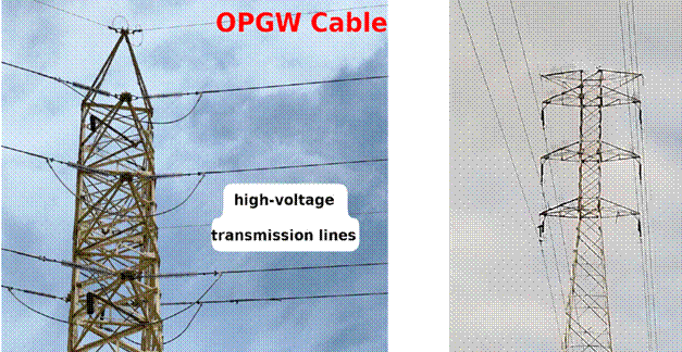
Composite fiber optic ground wires protect transmission lines from atmospheric discharge or lightning strikes, as they can lead to the interruption of the energy supply. During the last decade, the influence of atmospheric discharges on OPGW cables has been observed, noting considerable damages, ranging from the rupture of exposed cables to compromised mechanical resistance (Fig. 1). Optical fiber ground wires (OPGW) are designed to carry out two functions: the protection of power transmission lines from atmospheric discharges and data transmission via integrated fiber optics. OPGWs have gained considerable importance worldwide due to their double function, i.e., protection and communication. Thereupon, to ensure their capacity, electro-mechanical test methods focusing on reproducing extreme operating conditions have been developed.
Figure 1: This figure depicts a tower with an OPGW. The tower stands tall as a structural support for the OPGW and is designed to provide grounding and communication capabilities. This cable typically includes optical fibers for high-speed data transmission, and it is integrated with a metal sheath for grounding purposes, thereby ensuring the power transmission network’s structural stability and functional efficiency
1 simulated lightning strikes on OPGWs through an anode and a negative electrode that generated electrical impulses (discharges) between 100 and 200 Coulomb for 200 ms. The temperature distribution along the cable was monitored while considering heat release at the lightning strike’s position and using a distributed fiber optic temperature sensor (DOFTS). For the inner part of the OPGW, the temperature increase captured by the DOFTS was only several degrees Celsius. These experimental results also showed that the use of DOFTS has great potential for maintaining transmission lines, and that the transmission of electrical energy is not affected when lightning impacts generate less than 100 Coulomb. A similar project was carried out by 2, who proposed the use of DOFTS for better cable monitoring and maintenance, aiming to avoid potential risks leading to power outages or shortened operating times. Similar works have analyzed heat transfer and melting, as well as the breaking of wires in OPGWs 3. This has been done through direct current (DC) arc tests simulating lightning strikes to analyze melting and characterize the breakage of the wire strands. Said characterization involves the fusion of threads and the distribution of heat the transferred per area by an induced current arc of 1-100 kA. For these tests, the variables considered include current, duration (time), polarity, and gap length, in addition to size, type, and number of threads for cable selection.
Furthermore, 4 performed a mathematical analysis that predicted the melting and failure of wires in the face of lightning discharges simulated via 0.1-100 kA DC arcs, and 5 validated these conditions through various tests and mathematical thermal behavior models.
The work by 6 presented a comprehensive analysis based on the simulation of events with harmful effects such as electric shocks, short circuits, and wind-related incidents. Mathematical models, simulations, and thermomechanical sensors (DTS) placed along the OPGW fibers were used to determine their behavior. The cables were exposed to environmental factors such as wind, rain, humidity, and snow, as well as to the cooling/heating effects of short circuits and instantaneous current increases in the conductor phase - when OPGWs are exposed to these conditions, gradual insulation deformations take place.
In 7, the authors studied the experimental and numerical responses of the TF1000 under different wind loads. Moreover, 2 stated that cables suffer deterioration in frozen areas due to constant layers of ice, with deformations appearing when the additional tension is higher than 30 kN, potentially leading to fiber breakage. In 8, the effects of melting ice on the structure of a commercial and a modified OPGW supported by DOFTS were analyzed, examining the characteristics of the temperature distribution and variation due to the melting of ice on both OPGW cables.
The research presented in 9 proposed a comprehensive performance evaluation structure for transmission towers in power line systems. The authors considered the wind as the main factor of analysis, incorporating its speed and direction as well as the orientation of the lines. They proposed an optimal arrangement and used 50 years’ worth of statistical data on the wind in the area. With the OPGW grounded at each tower, the probability of lightning strikes and losses increased. Moreover, 10 suggested the use of these cables as lightning rods for power transmission lines, since lightning strikes are unavoidable and often cause cable unraveling or breakage. These accidents are serious threats to the transmission of information. The research confirmed that the high temperature of the electric arc and the effects of thunder are the main reasons for power line breakage.
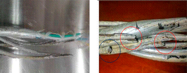
One of the main disturbances in this type of cable is the fraying of steel, generally associated with the presence and impact of atmospheric discharges that affect the wire, which is common in transmission lines located in critical areas (11). The work by (4) concluded that some metallic wires in power line ground cables (GW) and OPGWs sometimes melt and break from high-energy lightning strikes. The damage exhibits high concentrations of energy located at specific points of the wire, capable of melting and detaching cable strands (Fig. 2a). The effects caused by corrosion were also considered, as derived from the material used in the structure, which degrades due to inclement weather. In some cases, there were incrustations by the effects of load, in addition to corrosion, with the melting and loss of material observed in fault zones.
Figure 2: a) OPGW cable affected by an atmospheric discharge (Federal Electricity Commission) and guard cable with CFE optical fibers E1000-21. b) and c) Experimental results of controlled electrical discharges in the laboratory (11)
Fig. 2 shows the conditions potentially generated by atmospheric discharge in the cable, which involve high energy in short periods of time, or vice versa. It has been determined that the first case is associated with atmospheric discharges and the second with short-circuit conditions. The authors of (11) suggested that the damage increases linearly with the increase in charge transfer. As the discharge area increases, the intensity of the arc charge decreases. However, the volume of damage undergoes a non-monotonous change, which is due to complex variations in the area of attachment of the arc, regulated by the discharge space and the intensity of the current.
According to the Federal Electricity Commission, there were more than 967 failure events in the studied cable type in 2022 in Mexico (12). Attenuation was considered to be the main cause of failure. Specifically, 381 failure events related to attenuation were reported, as well as 51 to splice boxes, 189 to fiber optic cuts, and two to hardware. Failure by attenuation implies that optical fibers can no longer transmit data, with efforts, extreme temperatures, and external conditions being the main causes. Junction box failure occurs when wires are poorly tied. Fiber optic cuts are due to the different types of sudden events to which cables are exposed, and hardware failure primarily occurs when fastening in the towers does not coincide with the dimensions of the installed cable (13).
After reviewing the background on OPGWs and failure drivers, we will discuss some conditions to promote the development of procedures for the supervision, evaluation, and analysis of this cable type. The studied wires were exposed to atmospheric discharges causing their forced exit from transmission lines. Thereupon, one of the priorities was to know the effect of discharges on the electrical shielding of OPGWs in transmission towers at the national level. Regarding this specific case, we describe the methodology for analyzing a failed wire in one of the critical areas of the Republic of Mexico. The objective of this study is to investigate the performance and failure mechanisms of OPGWs under extreme environmental and mechanical conditions leading to rupture. By conducting comprehensive visual inspections, dimensional assessments, mechanical stress tests, and chemical analyses, this research aims to identify critical factors that contribute to the degradation and ultimate failure of OPGWs. The findings will provide valuable insights into improving design, material selection, and maintenance practices to enhance the durability and reliability of OPGWs in harsh operating environments.
Methodology
The proposed methodology also makes it possible to accurately assess the effects on the failed cable both at the location of the fault and close to it. The tests involved allow determining the causes of the damage and proposing precautionary measures. The case study includes a sample of a guard cable with an integrated fiber optic wire subdivided into two sections after the failure (Fig. 3a). Both sections are linked to failure by cable fraying, as observed in the fractured wires.
Figure 3: 36-wire OPGW. (a) Analyzed samples, sections A and B. (b) Guard cable with OPGW optical fibers, 36 single-mode fibers of class 0 for atmospheric discharge, category A for thermal dissipation. (1) Dielectric central element. (2) Thread to block water penetration. (3) Single-mode optical fibers. (4) Three thermoplastic tubes filled against water, each with 12 fibers. (5) Threads for blocking water penetration. (6) Aluminum tube. (7) 12 aluminum-coated steel wires, ∅=2.92 mm
There are several tests for this type of cable, both before commissioning and after failure. The methodology described herein includes the main tests stipulated in the regulations applied to OPGWs after failure:
-
Visual inspection is carried out at the macro and micro levels. In both sections of the wires, observation and detailed analysis of the fault zones are performed, for which a microscope is used as an adjunct. From this inspection, the type of failure (ductile or brittle), the incrustation of external agents, the level corrosion, and the material loss are obtained.
-
Dimensional inspection is a necessary technical test to ensure the quality and dimensional conditions under which the cable operates. This inspection records the current diameter of each wire, thereby obtaining melting and material loss values. Dimensions are measured using a Vernier caliper or a micrometer.
-
Mechanical stress. Mechanical tension is measured using a tension testing machine applied to each of the failed wires. It is defined as the mechanical behavior based on the effort against breaking times. Fitting the stress vs. time curve allows predicting the cable’s fatigue life, i.e., the number of cycles it can withstand before failure. It also helps to understand the cable’s elastic and plastic deformation behaviors over time. Sudden increases in stress or deviations from expected patterns can indicate potential failure points or areas that require maintenance. This test also allows understanding creep behavior and ensures that the cable maintains its integrity and performance over its expected service life. In critical applications, continuous monitoring of stress over time provides real-time data on cables’ structural health, enabling timely decisions to prevent failures.
-
Chemical analysis is used to identify the characteristics of the scale and corrosive elements in the cable. Scattered X-ray energy is used to this effect.
The analysis presented herein is based on 12 aluminum alloy wires surrounding the core of an OPGW cable, an element indicated as (7) in Fig. 3b. These aluminum alloy wires are made of 1350 aluminum-coated steel and support the OPGW’s cable structure. The samples were tested according to regulations and were 0.30 m long. The failed OPGW was a 36-fiber cable with a diameter of 16 mm and an energy transfer capacity of 50 Coulomb (C). Details are shown in Fig. 3b.
Results
As per regulations and standards, mechanical, optimal performance, and inspection tests are necessary to validate the quality and/or conditions of OPGWs. In this work, the physical, mechanical, and electrical characteristics of the individual wires in the cable samples were determined according to the specifications of the ASTM B230 (14) and ASTM B232 (15) standards. This specification covers the standard requirements for aluminum-alloy round wires for electrical purposes. Aluminum-alloy wires must be made from drawing stock and be free of brittleness, as evidenced by their ability to be coiled or looped around their diameter with or without a mandrel, as per the ASTM B232 standard. The tests described herein were selected according to their relevance in evaluating the studied cable type. As previously described, these standardized and regulated tests were based on visual inspection, dimensional inspection, mechanical stress assessment, and chemical analysis.
Visual inspection
Visual inspection was carried out at the macro and micro levels with the help of a microscope.
Gross observation
Section A comprises steel wires clad with aluminum, with deposits of corrosive agents exhibiting whitish and brown colorations due to the oxidation of the localized base material. In addition to the loss of material on the wire surface, the OPGW’s 12 crown wires show melting of the material and loss of coating from the point of failure up to distances of 0.40 m. A visual inspection was carried out before cutting the 0.30 m sections for the tension test. The ends of the wires showed a reduced cross-section in the failure zone, and 11 out of the 12 wires had sharp tips due to the loss of material and the type of failure. Moreover, the aluminum tube where the optical fibers were located exhibited a transverse reduction in the affected area. Fig. 4 shows the steel wires with aluminum coating in the crown, which exhibit wear and melting of the base material as well as sharp points. For section A, the aluminum tube containing the fibers showed a reduced diameter in the affected area - the reader should recall that this section includes three filaments with 12 optical fibers each (Figs. 5c and 5d). As observed in a close-up of the OPGW, there are fractures in some of the wires in the fault zones, mostly ductile faults and smelting due to atmospheric discharge, in addition to wires and material detachment in the fault zone, with some elements of oxidation and coating loss (Figs. 5a and 5b). Oxidation is observed in Figs. 5a, 5b, and 5c, as well as pitting of the coating and loss of material. Fig. 5 d shows the failed core tubing, which contains the optical fibers, in addition to a reduced cross-section due to mechanical stress. In the failed OPGW, clear signs of warming, short circuits, and cross-section reduction are also observed.
Figure 4: Left: failed section; right: fracture and material melting zone. Marked in red, sharp points can be observed
Figure 5: Affected area of the wires: a) oxidation and loss of material, b) loss of aluminum coating, c) oxidation and pitting of the coating as well as material loss, d) core tubing failure due to mechanical Stress
Section B of the failed sample indicates the loss of the aluminum-coated crown, which may be due to material melting. The tips of the wires have a reduced cross-section in the failure zone, and 10 of them have sharp points. One of the wires does not exhibit loss of area in it is cross-section due to brittle fault, and one more suggests a tool cut.
Fig. 6 shows the 12 failed OPGW wires. The visual analysis of each wire is summarized below:
Figure 6: Failed OPGW crown wires, section B
-
Wire 1 has a reduced cross-section as well as a fragile fracture footprint.
-
Wire 2 has a reduced cross-section and whitish deposits.
-
Wire 3 has a material release on the tip, and a lack of aluminum coating can be observed.
-
Wire 4 exhibits a fragile fracture pattern and temperature-induced material melting.
-
Wire 5 has a reduced cross-section and an almost completely melted tip.
-
Wire 6 exhibits a reduced cross-sectional area and fragile fault; coating loss is observed.
-
Wire 7 shows a reduced cross-section, and the tip shows signs of brittle failure. Signs of aluminum coating loss and temperature melting are also observed.
-
The cross-section and fragile footprint of wire 8 were minimally reduced, with minor deformation, but almost all of the aluminum coating was lost.
-
Wire 9 exhibits a reduced cross-section, leaving the tip sharp. It shows whitish deposits and signs of material loss due to casting.
-
Wire 10 shows a reduced cross-section area and a sharp tip. The observed material loss corresponds to more than 50 % of its section. There is also a lack of coating, and even the loss of much of the base material.
-
Wire 11 exhibits signs of tool cutting.
-
Wire 12 shows a minimal reduction of its cross-section area and fragile footprint, with minor deformation, but it shows signs of material detachment caused by high temperatures.
The darker wires suggest the effect of atmospheric discharge and thermal dissipation, as well as loss of coating and adhesion of polluting agents.
Microscopic inspection
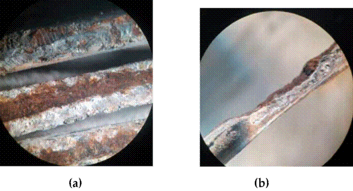
Corrosion zones were identified in the steel wires coated with aluminum, as well as embedded deposits of elements unrelated to the composition of the material. We also observed the melting and loss of material in the fault zone due to atmospheric discharge. Figs. 7a, 7b, and 14 show the close-up and microscopic inspection of the OPGW’s critical zones.
Figure 7: a) Crown wires with wear areas; b) total loss of aluminum layer and oxidation of the steel core
Dimensional inspection
Table I shows the dimensional inspection data of the crown wires in one of the samples, specifically in the failure zone. The diameter was measured to be nominal on outside and for each of the 12 wires
Table I: Dimensional inspection of the crown wires of the OPGW in the failure zone. The initial diameter corresponds to the cable in good condition. NA: wire core, DC: full cable, and TA: aluminum tubing.
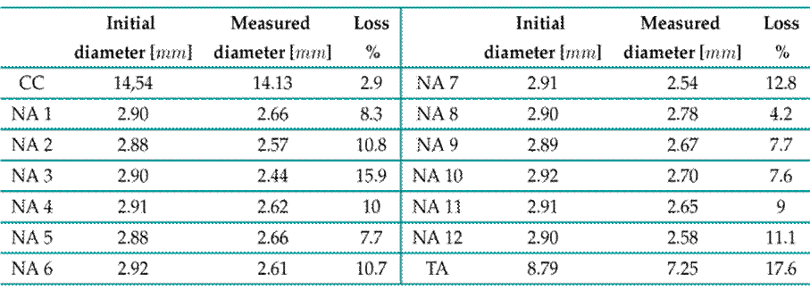
in the crown of the OPGW. For some manufacturers in the country, the nominal outer diameter is 14.65 mm, and the nominal weight is 0.575 kg/m. If storage time or conditions are to be considered, mass loss due to the reduction of the cross-section area constitutes a sign of the natural corrosion process. According to the manufacturer’s technical data, the average cable corrosion rate over 720 is 0.072 kg/m 2× year.
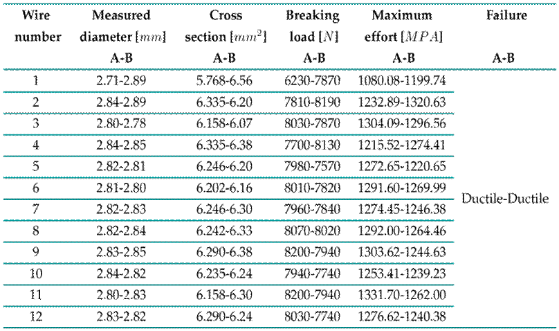
Table II shows the dimensions of the cables located in areas close to the rupture in sections A and B. Through the dimensional inspection of each element, diameter loss was observed, highlighting the need to corroborate the operating conditions of the cable in order to evaluate its mechanical behavior and determine its properties.
Table II: Results of the mechanical stress test for sections A and B, exterior crown
In addition, the tests conducted in this work allowed noting that the mechanical forces induced by the cable’s weight produce permanent deformations, and that temperature variations cause thermal deformations. Salinity, corrosion, and cable galloping also cause this type of deterioration. Although the properties were good in regions close to the failure zone, this deterioration was already noticeable.
Mechanical stress
Fig. 8 shows two cable sections (class 0, 0.30 m in length, as stipulated by the E1000_21 specification for stress testing). The elastic modulus (E) of the analyzed cable is around 116 Gpa. Table II analyzes the results of the mechanical tension tests, where each of the 12 wires was brought to break. On the left side, the results for section A show that the resistance to mechanical stress is maintained, with ductile failure under a very homogeneous load. It was expected that, due to its proximity to the fault, the material would be brittle and exhibit fragile faults as well as very uneven and lower load resistance results. In contrast, excellent cable quality was observed even after failure. The values on the right correspond to section B, and the results are similar.
Figure 8: 0.30 m long OPGW cable for tension tests, aluminum tube containing the optical fibers and their 12 test wires
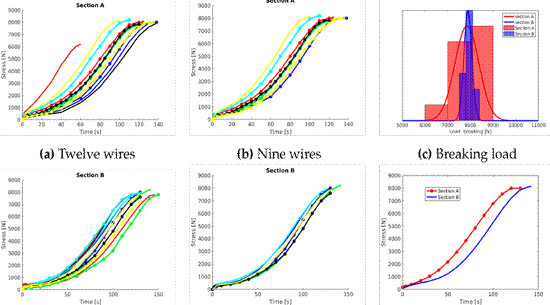
Among the results obtained in the stress tests, homogeneity was found between samples of sections A and B, with both preserving their mechanical properties and failing under similar values on average. Therefore, the cable was still in good condition before the sudden failure. The mechanical properties of the elements were slightly affected by the failure zone due to heating or specific corrosion. Fig. 12c shows the breaking load distribution in section A and B wires. The average breaking load of section A was µ A = 7846N, with a standard deviation of σ A = 528,22N, while, for section B, these values were µ B = 7889N and σ B = 171N.
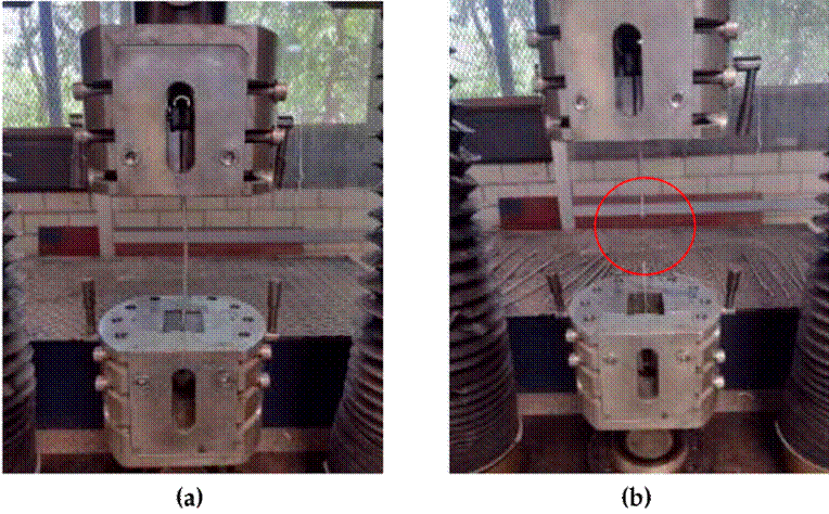
The test sequence was carried out using the JAUS universal machine (Fig. 9), applying a constant load at a speed of 5000 N/min. Test runs were performed for each of the wires from sections A and B. Fig. 9b shows one of the OPGW cable wires, which fails upon reaching the limit of its mechanical resistance to tension. The 30 ton JAUS vertical machine was located in a mechanical testing lab, and it had been calibrated by the laboratory of metrology.
Figure 9: OPGW cable wire tension test: a) universal tension machine at the start of the test; b) end of test upon failure
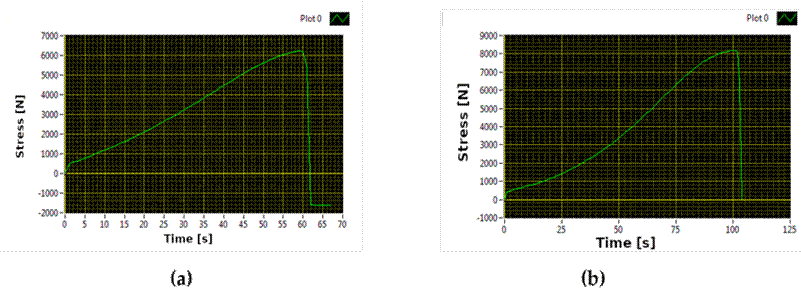
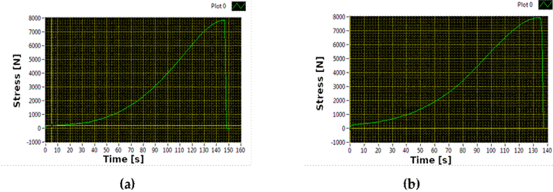
Test runs were performed for each of the wires that make up sections A and B. The mechanical stress results show the behavior of some of the outer wires in the OPGW cable crown upon applying a point load at a given time. Fig. 10 shows the load vs. time graph for cables 1 and 11 of section A. The graph for section B is presented in Fig. 11. These rupture values can be verified in Table II.
Figure 10: Point load vs. time graph for a) wire 1 and b) wire 11 of section A
Figure 11: Point load vs. time graph for a) wire 1 and b) wire 11 of section B.
The time until failure in most of the wires of sections A and B is close to 120 or 140 s, with some exceptions, such as wire 1 of section A, which failed within 60 s of applying the load according to the established parameters and execution speed. In both sections, a ductile and homogeneous failure behavior was observed, validating the quality of the analyzed cable.
Mechanical characterization
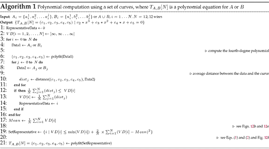
Figs. 12a and 12d present the stress vs. time graphs for the 12 cables in sections A and B, respectively. As part of the characterization of the cables’ behavior, we tested several polynomials, concluding that the fourth-order one best fitted the data. To determine the polynomial representation of the curves, this work proposes an algorithm that repeatedly computes a polynomial approximation using 12 distinct curves. To this effect, a fourth-order polynomial is generated for each curve. The algorithm then calculates the Euclidean distances from each curve point to the corresponding polynomial. Specifically, the average Euclidean distance for each curve is computed. The polynomial that best represents the set of curves is the one that minimizes said average distance. Ultimately, we used the polynomials within two times the standard deviation of the minimal distance and computed the entire section’s polynomial. This corresponds to the best representation of the curves, leaving those that have been physically affected aside. The detailed steps of the algorithm are outlined in 1.
Eqs. (1) and (2) represent the polynomial approximation of stress vs. time for sections A and B, respectively. For these equations, we considered the curves shown in Figs. 12b and 12e, which correspond to the SetRepresentative variable in Algorithm 1. Fig. 12f shows the polynomial approximation of Eqs. (1) and (2). The behavior of the cables exposed to discharges changes considerably, while those with little exposure maintain a similar behavior.
Figure 12: Stress vs. time graph. (a) and (d) show the 12 wires of section A and B. (b) and (e) were generated by removing the curvy cables at the top and bottom of the graph. (c) corresponds to the breakdown load distribution in section A and B wires, and (f) represents the polynomial approximation using the curves (b) and (e)
Chemical analysis
Once the tension tests had been carried out, we performed a chemical analysis. Through dispersive X-ray, the energy of a healthy wire was scanned, validating that the sample corresponded to an aluminum alloy. Fig. 13 shows, as a percentage, the base elements on the surface: Al (96.9 %), Cu (1.7 %), Fe (0.9 %), and Si (0.5 %). The analyzed sample was named Spectrum 66.
Figure 13: Elemental chemical analysis of the crown that makes up the OPGW
In the images of Fig. 14, a wire of the OPGW is seen to be visibly affected, with signs of pitting and a reduced cross-section. With prior verification through visual, dimensional, and microscopic inspection, a few bites were analyzed, corroborating the presence of corrosive agents, in addition to quantifying the loss of base material.
Figure 14: Zoom-in of the red zone of a visibly affected wire, with signs of pitting and corrosion. The chemical analysis of this zone is shown in Fig. 15
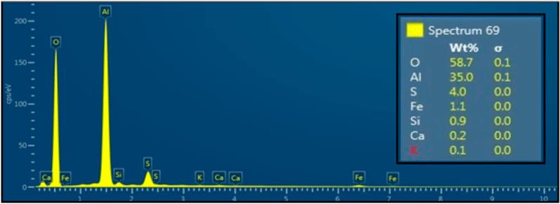
The chemical analysis of the pitting area defined as Spectrum 69 can be observed in Fig. 15. The results indicate a high concentration of oxide due to the amount of oxygen recorded (58.7 %), which suggests an accelerated process regarding the natural oxidation of the base material (Fe), observed in the form of a reddish-brown coloration. In this case, natural oxidation was mostly generated by humidity and environmental conditions. The deposits attached to the wire’s aluminum contained highly corrosive elements concentrated in the pitting area, such as sulfur (S), i.e., up to 4 %, which is a large amount of corrosive agent. The percentage of coating on the wire, which should remain above 90 % (Al), was 35 %, indicating losses. Therefore, the health of the element’s coating was affected by the operating conditions.
The guard wire with optical fibers exhibited reduced electrical properties and mechanics in this area.
Figure 15: Elemental chemical analysis of pitting in the OPGWs
The deposits adhered to the wires were also identified. The aluminum coating contained corrosive elements such as S and Na in the zone of base material loss, and we observed the loss of the covering layer and a significant percentage of oxygen due to the oxidation process caused by environmental and industrial impacts. The agents usually come from industrial areas and combine with oxygen and moisture in the environment, leading to the formation of acids and hydroxides that act as corrosive agents and accelerate the degradation of the material. These corrosive agents act mainly on the galvanized steel wires that make up the core of the cable, aggressively deteriorating their Zn layer, penetrating into the base material. With the above, a material loss process takes place, decreasing the wire’s diameter and inducing a stress concentration on the driver element. The area decrease generates a temperature increase in the wires, as current is conducted through a smaller cross-section. Under these conditions, wires subjected to combined electromechanical and thermal stress can gradually yield, resulting in rupture.
Discussion of the results and recommendations
OPGWs must meet standards and requirements based on physical, electric, mechanical, and optical aspects. Recent research in this field has focused on electrical aspects, e.g., the continuous monitoring and maintenance of voltage transmission lines. These studies have used cable samples exposed to atmospheric discharge, which have been reproduced in laboratory settings 2) (3), (10), (16), (17)). Multiple consecutive lightning strikes on OPGWs have been achieved using impulse and direct current 11, resulting in conditions such as arc sweep, melting, and ablation damage, affecting the internal optical fiber.
As for the mechanical aspects, the analysis performed involved continuously monitoring thermal behavior and melting in the face of induced atmospheric discharges 1) (3) (18. The mechanical and electrical analyses were directly related 4) (11) (16), (19)). To validate the mathematical analysis aimed at predicting cable melting or failure, it was necessary to produce atmospheric discharges. In this research project, the tests were mechanical. In Latin America, there are few certified laboratories for testing OPGWs, where an average of 12 standardized tests are carried out on them, 10 mechanical and two electrical. The laboratory in which our tests took place has the certification, standards, and requirements necessary for development and evaluation.
For 3, as in this research, determining the characteristics (including cable classification and class) of OPGWs is essential for installation in specific regions. The authors of 18 tested various commercial cables while considering critical factors such as their material, thermal properties, and structure. For this project, the type of cable and the arrangement of the wires in the crown and the material were also necessary. With the reference data offered by the manufacturer, the performance and quality after failure of OPGWs in a coastal area were analyzed through mechanical tests. These tests were fundamental to determining the cause of failure and ascertaining whether the type of failed cable was a suitable option for installation.
2 determined that these cables have greater rigidity, which is suitable for icy conditions or freezing. This causes a phenomenon known as galloping, wherein the wires start to deform at 30 kN or below due to creeping. Since some manufacturers consider operating temperature ranges of -40 to 70 o C to be correct, it is interesting to analyze this type of cable regarding its degree of affectation by extreme cold. For comparison with the aforementioned value of 30 kN, according to Table II, the breaking load of each of the 12 wires is 8 kN on average. National manufacturers and the Federal Electricity Commission’s technical specification indicate that OPGWs’ breaking value is around 78 kN, so it is essential to carry out more tests to determine the properties of these cables after failure events.
As technical recommendations, because atmospheric discharges are the cause for many transmission line failures, it is paramount to understand the effect they cause on cable shielding in transmission towers at the national level. Nowadays, atmospheric discharges account for 45 % of failures at voltage levels of 69-400 kV (13). Therefore, using good shielding in electrical systems helps to significantly reduce the damage caused by atmospheric discharges. This shielding must be excellent and based on the grounding system design of each tower, and it must consider the recommended design resistivity. According to the CFE 00J00-52 specification, the grounding resistivity must generally be less than or equal to 10 Ω (13).
Conclusions
This research addresses the issues caused by lightning strikes on transmission lines, which tend to impact OPGW guard cables.
A sample of failed OPGWs was acquired from a transmission line located in the coastal area of Valladolid, Yucatán, Mexico (DZT-A360-RXXY-LT 400 kV line). The samples were divided into sections, A and B, whose properties and conditions after cable failure were analyzed. The failure zone was also studied. The tests carried out were visual and dimensional inspection and mechanical stress and chemical tests. Some lightning strike points were preliminarily marked as the main causes of OPGW breakage.
For sections A and B, each of the 12 wires behaved similarly, mostly exhibiting ductile failures and a reduced cross-section. The preservation of the mechanical properties in the wires at a minimum distance of 0.40 m from the failure zone indicates that the cable still was in good conditions before the atmospheric discharge. According to the chemical analysis, despite the changes in structure, the cable maintained operational mechanical properties even near the failure zone, demonstrating the quality of the cable. Furthermore, deposits of corrosive agents were found, which were minimal and located in the fault zone. The cable type analyzed failed due to a lightning strike, but, according to the chemical and visual tests, it already had signs of corrosion.
Our zonal analysis concluded that the two main causes for failure were atmospheric discharge and natural, gradual corrosion. The former caused a considerable absorption of the energy produced by the electric arc generated on the OPGW. The rupture occurred when the cable was mechanically weakened by the progressive deterioration of the wires and exposed to corrosive agents that modified their physical characteristics, exhibiting material loss and a reduced cross-section, in addition to initiating a stress concentration. Atmospheric discharge also affected the cable’s properties by means of an abrupt temperature rise that modified the molecular structure of some of the wires, stiffening or melting them. The strain exerted by the cable’s weight was also influential.
The observed corrosion was caused by deposits of the corrosive agents described in the chemical analysis. These agents originate from natural sources or pollutants generated in industrial areas. When combined with oxygen and moisture from the environment, they produce acids and hydroxides that corrode and accelerate the degradation of the material.
Regarding the mechanical stress tests, it was possible to elaborate stress vs. time graphs using a fourth-order polynomial. The polynomial characterization of most wires in sections A and B proved to be uniform. This uniformity confirms the excellent mechanical conditions of these cable sections, even though they were located near the fault zone, and lays the groundwork for the characterization of this type of cables.
The purpose of this analysis methodology was to determine the quality of OPGWs after failure. There are different OPGW qualities, as well as arrangements, materials, and classes. This research provides a basis for future research to categorize region-specific cable characteristics according to already established tests. The selection of the necessary cable characteristics should be based on extreme regions, such as those with prevailing winds, icy climates, highly corrosive environments (e.g., marine, coastal, and industrial areas), or common atmospheric discharges. Thus, despite that the studied site is a coastal area, the evidence allowed concluding that the appropriate cable had been installed
References
Licencia
Derechos de autor 2024 Erick-Alejandro González-Barbosa, Fernando Jurado-Pérez, Jose-Joel Gonazlez-Barbosa, Julio Cesar Méndez-Gutiérrez

Esta obra está bajo una licencia internacional Creative Commons Atribución-NoComercial-CompartirIgual 4.0.
A partir de la edición del V23N3 del año 2018 hacia adelante, se cambia la Licencia Creative Commons “Atribución—No Comercial – Sin Obra Derivada” a la siguiente:
Atribución - No Comercial – Compartir igual: esta licencia permite a otros distribuir, remezclar, retocar, y crear a partir de tu obra de modo no comercial, siempre y cuando te den crédito y licencien sus nuevas creaciones bajo las mismas condiciones.











2.jpg)


