DOI:
https://doi.org/10.14483/23448393.16925Published:
2020-10-02Issue:
Vol. 25 No. 3 (2020): September - DecemberSection:
Special Section: Best Extended Articles - WEA 2015Optimal Placement of Capacitors, Voltage Regulators, and Distributed Generators in Electric Power Distribution Systems
Ubicación óptima de capacitores, reguladores de tensión y generadores distribuidos en sistemas eléctricos de distribución
Keywords:
Capacitor Banks, distributed generation, distribution networks, voltage regulators (en).Keywords:
Bancos de capacitores, generaci´on distribuida, redes de distribución, regularores de tensi´on. (es).Downloads
References
J. F. Franco, M. J. Rider, M. Lavorato, and R. Romero, “A mixed-integer LP model for the optimal allocation of voltage regulators and capacitors in radial distribution systems”, Int. J. Elec. Pow. E. Sys., vol. 48, no. 1, pp. 123-130, 2013, https://doi.org/10.1016/j.ijepes.2012.11.027
R. A. Gallego, A. J. Monticelli, and R. Romero, “Optimal capacitor placement in radial distribution networks”, IEEE Transac. Pow. Sys., vol. 16, no. 4, pp. 630-637, 2001, https://doi.org/10.1109/59.962407
W. H. Kersting, Distribution System Modelling and Analysis, Boca Raton, FL, USA: CRC press, 2001.
M. J. Rider, A. V. Garcia, and R. Romero. Transmission system expansion planning by a branch-and-bound algorithm, IET Gen. Trans. Dist., vol, 2, no. 1, pp. 90-99, 2008, https://doi.org/10.1049/iet-gtd:20070090
S. Binato, M. V. F. Pereira, and S. Granville, “A New Benders Decomposition Approach to Solve Power Transmission Network Design Problems”, IEEE Transac. Pow. Sys., vol. 16, no. 2, pp. 235-240, 2001, https://doi.org/10.1109/59.918292
G. Levitin, A. Kalyuzhny, A. Shenkman, and M. Chertkov, “Optimal capacitor allocation in distribution systems using a genetic algorithm and a fast energy loss computation technique”, IEEE Transac. Pow. Del., vol. 15, no. 2, pp. 623-628, 2000, https://doi.org/10.1109/61.852995
M. Ayoubi, R. A. Hooshmand, and M. Torabian Esfahani, “Optimal capacitor placement in distorted distribution systems considering resonance constraint using multi-swarm particle swarm optimisation algorithm”, IET Gen. Trans. Dist., vol. 11, no. 13, 3210-3221, 2017, https://doi.org/10.1049/iet-gtd.2016.0989
H. S. Ramadan, A. F. Bendary, and S. Nagy, “Particle swarm optimization algorithm for capacitor allocation
problem in distribution systems with wind turbine generators”, Int. J. Elec. Pow. E. Sys., vol. 84, supplement C, pp. 143-152, 2017, https://doi.org/10.1016/j.ijepes.2016.04.041
R. Sirjani, A. Mohamed, and H. Shareef, “Optimal capacitor placement in a radial distribution system using Harmony Search algorithm”, J. App. Sc., vol. 10, no. 23, pp. 2998-3006, 2010, https://doi.org/10.3923/jas.2010.2998.3006
C.-F. Chang, “Reconfiguration and capacitor placement for loss reduction of distribution systems by ant colony search algorithm” IEEE Transac. Pow. Sys., vol. 23, no. 4, pp. 1747-1755, 2008, https://doi.org/10.1109/TPWRS.2008.2002169
R. Annaluru, S. Das, and A. Pahwa, “Multi-level ant colony algorithm for optimal placement of capacitors in distribution systems”, Pro. 2004 Con. Evol. Comp. (IEEE Cat. No.04TH8753), vol. 2, pp. 1932-1937, 2004, https://doi.org/10.1109/CEC.2004.1331132
Y.-T. Hsiao, Ch.-H. Chen, and Ch.-Ch. Chien, “Optimal capacitor placement in distribution systems using a combination fuzzy-GA method”, Int. J. Elec. Pow. E. Sys., vol. 26, pp. 501-508, 2004, https://doi.org/10.1016/j.ijepes.2004.01.002
A. A. El-Fergany and A. Y. Abdelaziz, “Capacitor allocations in radial distribution networks using cuckoo search algorithm”, IET Gen. Trans. Dist., vol. 8, no. 2, pp. 223-232, 2014, https://doi.org/10.1049/iet-gtd.2013.0290
Sh. J. Huang, “An immune-based optimization method to capacitor placement in a radial distribution system”, IEEE Transac. Pow. Del., vol. 15, no. 2, pp.744-749, 2000, https://doi.org/10.1109/61.853014
S. Sultana and P. K. Roy, “Optimal capacitor placement in radial distribution systems using teaching learning based optimization”, Int. J. Elec. Pow. E. Sys., vol. 54, pp. 387-398, 2014, https://doi.org/10.1016/j.ijepes.2013.07.011.
S. Civanlar and J. J. Grainger, “Volt/Var Control on Distribution Systems with Lateral Branches Using Shunt Capacitors and Voltage Regulators Part I: The Overall Problem”, IEEE Transac. Pow. App. and Sys., vol. PAS-104, no. 11, pp. 3278-3283, 1985, https://doi.org/10.1109/TPAS.1985.318842.
S. Civanlar and J. J. Grainger, “Volt/var control on distribution systems with lateral branches using shunt capacitors and voltage regulators part II: The solution method”, IEEE Transac. Pow. App. and Sys., vol. PAS-104, no. 11 3284-3290, 1985, https://doi.org/10.1109/TPAS.1985.318843.
S. Civanlar and J. J. Grainger, “Volt/Var Control on Distribution Systems with Lateral Branches Using Shunt Capacitors and Voltage Regulators Part III: The Numerical Results”, IEEE Transac. Pow. App. and Sys., vol. PAS-104, no. 11, pp. 3291-3297, 1985, https://doi.org/10.1109/TPAS.1985.318844.
J. Sugimoto, R. Yokoyama, Y. Fukuyama, V. V. R. Silva, and H. Sasaki, “Coordinated allocation and control of voltage regulators based on reactive tabu search”, in 2005 IEEE Russia Pow. Tech., pp. 1-6, 2005, https://doi.org/10.1109/PTC.2005.4524739.
G. Carpinelli, C. Noce, D. Proto, and P. Varilone, “Voltage regulators and capacitor placement in three-phase distribution systems with non-linear and unbalanced loads”, Int. J. of Emer. Elec. Pow. Sys., vol. 7, no. 4, 2006, https://doi.org/10.2202/1553-779X.1353.
E. Pereira Madruga and L. Neves Canha, “Allocation and integrated configuration of capacitor banks and voltage regulators considering multi-objective variables in smart grid distribution system”, in 2010 9th IEEE/IAS Int. Con. Ind. App., INDUSCON 2010, pp. 1-6, 2010, https://doi.org/10.1109/INDUSCON.2010.5740055.
B. A. de Souza and A. M. F. de Almeida, “Multiobjective optimization and fuzzy logic applied to planning of the volt/var problem in distributions systems”, IEEE Transac. Pow. Sys., vol. 25, no. 3, pp. 1274-1281, 2010, https://doi.org/10.1109/TPWRS.2010.2042734.
I. Szuvovivski, T. S. P. Fernandes, and A. R. Aoki, “Simultaneous allocation of capacitors and voltage regulators at distribution networks using Genetic Algorithms and Optimal Power Flow”, Int. J. Elec. Pow. E. Sys., vol. 40, no. 1, pp. 62-69, 2012, https://doi.org/10.1016/j.ijepes.2012.02.006.
N. Khalesi, N. Rezaei, and M.-R. Haghifam, “DG allocation with application of dynamic programming for los reduction and reliability improvement”, Int. J. Elec. Pow. E. Sys., vol. 33, no. 2, pp. 288- 295, 2011, https://doi.org/10.1016/j.ijepes.2010.08.024.
L. F. Ochoa and G. P. Harrison, “Minimizing energy losses: Optimal accommodation and smart operation of renewable distributed generation”, IEEE Transac. Pow. Sys., vol. 26, no. 1, pp. 198-205, 2011, https://doi.org/10.1109/TPWRS.2010.2049036.
M. J. Rider, J. M. Lopez-Lezama, J. Contreras, and A. Padilha-Feltrin, “Bilevel approach for optimal location and contract pricing of distributed generation in radial distribution systems using mixed-integer linear programming”, IET Gen. Trans. Dist., vol. 7, no. 7, pp. 724-734, 2013, https://doi.org/10.1049/iet-gtd.2012.0369.
Q. Kang, T. Lan, Y. Yan, L. Wang, and Q. Wu, “Group search optimizer based optimal location and capacity of distributed generations”, Neurocomputing, vol. 78, no. 1, pp. 55-63, 2012, https://doi.org/10.1016/j.neucom.2011.05.030.
N.-C. Yang and T.-H. Chen, “Evaluation of maximum allowable capacity of distributed generations connected to a distribution grid by dual genetic algorithm”, En. Build., vol. 43, no. 11, pp. 3044-3052, 2011, https://doi.org/10.1016/j.enbuild.2011.07.025.
F. S. Abu-Mouti and M. E. El-Hawary, “Optimal distributed generation allocation and sizing in distribution systems via artificial bee colony algorithm”, IEEE Transac. Pow. Del., vol. 26, no. 4, pp. 2090-2101, 2011, https://doi.org/10.1109/TPWRD.2011.2158246.
M. Junjie, W. Yulong, and L. Yang, “Size and location of distributed generation in distribution system based on immune algorithm”, Sys. Eng. Proc., vol. 4, pp. 124-132, 2012, https://doi.org/10.1016/j.sepro.2011.11.057.
S. Saha and V. Mukherjee, “Optimal placement and sizing of dgs in rds using chaos embedded sos algorithm”, IET Gen. Trans. Dist., vol. 10, no. 14, pp. 3671-3680, 2016, https://doi.org/10.1049/iet-gtd.2016.0151.
A. F. Pérez Posada, J. G. Villegas, and J. M. López-Lezama, “A Scatter Search Heuristic for the Optimal Location, Sizing and Contract Pricing of Distributed Generation in Electric Distribution Systems”, Energies, vol. 10, no. 10, pp. 1449, 2017, https://doi.org/10.3390/en10101449.
B. R. Pereira, G. R. M. da Costa, J. Contreras, and J. R. S. Mantovani, “Optimal distributed generation and reactive power allocation in electrical distribution systems”, IEEE Transac. Sust. En., vol. 7, no. 3, pp. 975-984, 2016, https://doi.org/10.1109/TSTE.2015.2512819.
M. Pesaran H. A., P. Dang Huy, and V. K. Ramachandaramurthy, “A review of the optimal allocation of distributed generation: Objectives, constraints, methods, and algorithms”, Renew. Sust. En. Rev., vol. 75, supplement C, pp. 293-312, 2017, https://doi.org/10.1016/j.rser.2016.10.071.
K. Suvarchala, T. Yuvaraj, and P. Balamurugan, “A brief review on optimal allocation of distributed generation in distribution network”, in 2018 4th Int. Con. on Elec. En. Sys. (ICEES), pp. 391-396, 2018, https://doi.org/10.1109/ICEES.2018.8443294.
S. P. Singh and A. R. Rao “Optimal allocation of capacitors in distribution systems using particle swarm optimization”, Int. J. Elec. Pow. E. Sys., vol. 43, no. 1, pp. 1267-1275, 2012, https://doi.org/10.1016/j.ijepes.2012.06.059.
D. Quoc Hung, N. Mithulananthan, and R. C. Bansal, “Analytical expressions for DG allocation in primary distribution networks”, IEEE Transac. En. Conv., vol. 25, no. 3, pp. 814-820, 2010, https://doi.org/10.1109/TEC.2010.2044414.
N. Acharya, P. Mahat, and N. Mithulananthan, “An analytical approach for dg allocation in primary distribution network”, Int. J. Elec. Pow. E. Sys., vol. 28, no. 10, pp. 669-678, 2006, https://doi.org/10.1016/j.ijepes.2006.02.013.
F. Rotaru, G. Chicco, G. Grigoras, and G. Cartina, “Two-stage distributed generation optimal sizing with clustering-based node selection”, Int. J. Elec. Pow. E. Sys., vol. 40, no. 1, pp. 120-129, 2012, https://doi.org/10.1016/j.ijepes.2012.02.012.
J. Tu, Y. Xu, and Z. Yin, “Data-Driven Kernel Extreme Learning Machine Method for the Location and Capacity Planning of Distributed Generation”, Energies, vol. 12, no. 1, pp. 109, 2019, https://doi.org/10.3390/en12010109.
C. S. Cheng and D. Shirmohammadi, “A three-phase power flow method for real-time distribution system analysis”, IEEE Transac. Pow. Sys., vol. 10, no. 2, pp. 671-679, 1995, https://doi.org/10.1109/59.387902.
M. E. Baran and F. F. Wu, “Optimal sizing of capacitors placed on a radial distribution system”, IEEE Transac. Pow. Del., vol. 4, no. 1, pp. 735-743, 1989, https://doi.org/10.1109/61.19266.
Y.-C. Huang, H.-T. Yang, and C.-L. Huang, “Solving the capacitor placement problem in a radial distribution system using Tabu Search approach”, IEEE Transac. Pow. Sys., vol. 11, no. 4, pp. 1868-1873, 1996, https://doi.org/10.1109/59.544656.
How to Cite
APA
ACM
ACS
ABNT
Chicago
Harvard
IEEE
MLA
Turabian
Vancouver
Download Citation
Recibido: 1 de junio de 2020; Revisión recibida: 31 de agosto de 2020; Aceptado: 15 de septiembre de 2020
Abstract
Context:
With the advent of the smart grid paradigm, electrical distribution network (EDN) operators are making efforts to modernize their power grids through the optimal implementation of distributed generators (DGs) and other devices such as capacitors (CAs) and voltage regulators (VRs). The optimal allocation of such devices is a challenging task involving discrete and integer decision variables.
Method:
This paper presents an approach for the optimal placement of CAs, VRs and DGs in EDNs. The distinctive feature of the proposed model is the fact that it can be used to optimize the allocation of all of these elements together, in pairs, or separately. The optimal implementation of these elements is formulated as a mixed integer nonlinear programming (MINLP) problem, and it is solved by means of a specialized genetic algorithm (SGA).
Results:
The proposed methodology was tested on the IEEE 69-bus test system. The results were compared with previous works from the specialized literature, showing the effectiveness and robustness of the model.
Conclusions:
It was found that the appropriate allocation of CAs, VRs, and DGs results in a significant power loss reduction. It was also found that the proposed model is faster than other techniques proposed in the specialized literature.
Keywords:
capacitor banks, distributed generation, distribution networks, voltage regulators..Resumen
Contexto:
Con la llegada del paradigma de las redes inteligentes, los operadores de redes de distribución eléctrica (RDE) están haciendo esfuerzos para modernizar sus redes a través de la implementación óptima de generadores distribuidos (GDs) y otros dispositivos como condensadores (CAs) y reguladores de tensión (VRs). La ubicación óptima de estos dispositivos es una tarea desafiante que involucra variables de decisión discretas y enteras.
Método:
Este artículo presenta una metodología para la colocación óptima de CAs, VRs y GDs en RDEs. La característica distintiva del modelo propuesto es el hecho de que se puede utilizar para optimizar la ubicación de todos estos elementos a la vez, en pares o por separado. La implementación óptima de estos elementos se formula como un problema de programación no lineal de enteros mixta (PNLEM), y se resuelve mediante un algoritmo genético especializado (AGE).
Resultados:
La metodología propuesta se probó en el sistema de prueba IEEE de 69 barras. Los resultados se compararon con trabajos previos de la literatura especializada, mostrando la efectividad y robustez del modelo.
Conclusiones:
Se encontró que la ubicación adecuada de CAs, VRs y GDs resulta en una reducción importante de pérdidas de energía. También se encontró que el modelo propuesto es más rápido que otras técnicas propuestas en la literatura especializada.
Palabras clave:
bancos de capacitores, generación distribuida, redes de distribución, reguladores de tensión.Introduction
The expansion planning of capacitors (CAs), voltage regulators (VRs), and distributed generators (DGs) in electrical distribution networks is carried out to achieve one or more of the following objectives: 1) power loss reduction 2) voltage profile improvement, 3) power factor correction, and 4) increasing circuit capacity [1]. The optimal allocation of these components can be formulated as a mixed integer nonlinear programming (MINLP) problem. This problem exhibits high mathematical complexity and involves the phenomenon of combinatorial explosion, which means that the number of possible solutions grows exponentially with the size of the electrical network [2].
The challenge of optimally placing CAs, VRs, and DGs consists of determining their type, quantity, locations, active and reactive power injections, and position of taps (for VRs) that must be set up in a distribution network with minimum investment cost to address a forecasted demand. Several mathematical optimization techniques have been reported to solve the optimal placement of CAs, VRs, and DGs either separately or together. [3]
Given specific conditions such as differentiability and convexity, exact algorithms have the ability to find the global optimal solution of the problem under study. These algorithms include Branch and Bound, decomposition, and cutting methods [4], [5]. In most power system applications, the implementation of such algorithms requires a process with high mathematical complexity [1].
Metaheuristic algorithms, on the other hand, are designed to deal with non-linear, non-convex, and multi-modal optimization problems such as the optimal allocation of elements in distribution networks. These techniques have been used to solve the optimal placement of CAs, VRs, or DGs, and they are able to find high-quality solutions and even, in some cases, global optimal solutions with low computational effort. Traditionally, the allocation of DGs has been treated independently from the allocation of CAs and VRs. There are many studies regarding the proper allocation of both CAs and VRs. These methods include Tabu Search (TS) [2], genetic algorithms (GAs) [6], particle swarm optimization (PSO) [7], [8], harmony search (HS) [9], ant colony optimization (ACO) [10], [11] the combination of genetic algorithms and fuzzy logic [12], cuckoo search (CS) [13], immunebased optimization algorithms [14], and clustering-based optimization (CBO) [15], among others.
The expansion planning of CAs and VRs in electrical distribution networks is important for controlling the voltage profile, mainly in heavily loaded feeders, where there might be voltage drop issues. The optimal sizing, location, and control of VRs and CAs in distribution networks have been addressed by some studies [16] -[18], where each problem is solved separately. Moreover, these problems can also be considered jointly as in [1], where the optimal placement of CAs and VRs was modeled as a “Mixed Integer Linear Programming (MILP)” problem for radial networks. Sugimoto, Yokoyama, and Fukuyama [19], proposed the allocation and control of VRs through TS, and GAs were applied in [20] -[23] to solve the optimal placement of both CAs and VRs. In most of these references, the model is formulated as a MILP problem, and different load levels are considered.
Regarding distributed generation, several studies have been conducted for its proper integration in distribution systems. For instace, methods based on classical mathematical programming are explored in [24] -[26]. Usually, these methods resort to a linearized model of the network, ignoring the reactive component. Metaheuristic methods have proven to be effective in finding high-quality solutions to the problem of optimal allocation and sizing of DGs. These methods include PSO [27], GAs [28], artificial bee colony algorithms [29], immune algorithms [30], TS [31], scatter search algorithms [32], and chaotic algorithms [33], among others. Reviews regarding the optimal allocation of DGs can be consulted in [34] and [35].
Table I presents a brief summary of the main studies reported in the specialized literature regarding the expansion planning of CAs, VRs, and DGs in electrical distribution networks (EDNs). A distinctive feature of this work is the fact that it considers the allocation of all these elements together in a single optimization approach.
Table I: Optimal allocation of VRs, CAs and DGs in EDNs

This paper proposes a specialized genetic algorithm (SGA) to solve the optimal implementation of CAs, VRs, and DGs. The main characteristics of an SGA are summarized as follows: 1) the objective function is divided into a Fitness and Penalty functions, where the former represents investment and operational cost, while the later penalizes violations of network constraints; 2) only one individual or candidate solution is created in each iteration, which must be different from all individuals of the current population; 3) throughout an iterative process, the best individuals are preserved; and 4) a local intensive search is performed in each iteration to check for better individuals. The main contribution of this paper consists on a novel modeling and solution approach for the optimal implementation of CAs, VRs, and DGs as fundamental elements of the expansion planing of EDNs. In contrast with traditional approaches that consider the allocation of one or two types of these devices, this paper deals with the joint optimal allocation of CAs, VRs, and DGs. Moreover, both fixed and switchable capacitors are considered, and the optimal allocation of CAs, VRs, and DGs can be performed considering all types of elements together: by pairs or separately. Regarding distributed generation, the codification of the SGA provides both the optimal sizing and dispatch of DGs for every load level under consideration. Finally, the proposed approach is easy to implement, and due to its robustness and effectiveness, it can be applied in real-size distribution systems.
This paper is organized as follows: in Section 2, the proposed mathematical modeling is presented; then, the SGA used to solve the optimal placement of CAs, VRs, and DGs is described in Section 3; Section 4 presents the tests and results, as well as a comparative analysis with other works reported in the specialized literature; and, finally, conclusions are presented in Section 5.
Mathematical modeling
This section presents the proposed mathematical modeling for the optimal allocation of CAs, VRs, and DGs in EDNs. For the sake of simplicity, the representation of the steady-state operation of the EDNs under study is performed under the following hypotheses: 1) loads are modeled as constant power injections; 2) EDNs are represented by their single-phase equivalent; 3) real and reactive power losses on branch ij are concentrated in node i; 4) only one type of capacitor (either fixed or switched) is permitted to be installed at a given bus.
The optimal placement of CAs, VRs, and DGs in EDNs can be formulated as an MINLP problem as follows:
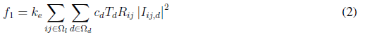
Equation (1) represents the objective function that consists of minimizing the investment cost of new elements (CAs, VRs, and GDs), and the operation cost of the network (power loss cost). This function consists of five terms. The first term, given by Equation (2) and lableled as f1, represents the cost of power losses. The second and third terms, given by Equations (3) and (4), labeled as f2 and f3, respectively, are the investment cost of installing fixed and switched capacitors. The fourth term, given by Equation (5) and labeled as f4, is the investment cost of installing VRs. Finally, the fifth term, given by Equation (6) and labeled as f5, represents the investment cost of installing DGs. Parameters k cp , k vr , and k dg convert the present investment value into equal annual payments over a specified time, at a specified discount rate or interest. Parameter k e is the interest rate of the total cost of power losses.

where:


Equations (7) and (8) represent the active and reactive power balance constraints. Equation (9) is the voltage drop at branch ij for the load level d. Equation (10) represents the apparent power flow at branch ij for the load level d. Equations (11) and (12) represent the limits on active and reactive power injection of a substation located at node i. Equations (13) and (14) represent the voltage and current limits in every load level d, respectively. Equations (15) and (16) represent active and reactive power injection limits of a DG located at node i, for the load level d. Equations (17)-(21) describe the VR modeling. Equations (22)-(28) correspond to the maximum number of elements that can be added to the network (fixed and switched CA, VRs, and DGs, respectively). Equations (29)-(32) are constraints of binary nature for allocation of fixed or switched capacitors, voltage regulators, and distributed generators, respectively. An element is placed if the corresponding value is equal to one and is not placed if it is equal to zero.
s.t:


The model described above represents a nonlinear multimodal problem which can be better handled by metaheuristic techniques. In this case, an SGA was developed to find high quality solutions to the problem. Such SGA is described below.
Specialized Genetic Algorithm (SGA)
Genetic algorithms are methodologies that can solve combinatorial optimization problems of high mathematical complexity with low computational effort. In this paper, a specialized genetic algorithm (SGA) is used to solve the optimal placement of CAs, VRs, and DGs. Fig. 1 presents the flowchart of the proposed SGA. The flowchart shows several control parameters, such as: k ps , k sr , k mr , k max , and k of , which are population size, selection rate, mutation rate, maximum number of iterations, and maximum number of iterations without improvement of the objective function (incumbent), respectively.
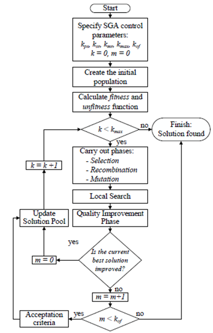
Figure 1: Flowchart of the proposed SGA.
Codification
The codification of the SGA is illustrated in Fig. 2. An individual of the population (also known as solution candidate or configuration) is represented by a matrix of size nd X nt, where nd represents the load levels, and nt is equal to: the number of candidate buses (nb) where fixed CAs can be allocated, plus the number of candidate buses (nb) where switched CAs can be allocated, plus the number of candidate lines (nl) where VRs can be allocated, plus the number of candidate buses (nb) where DGs can be allocated.
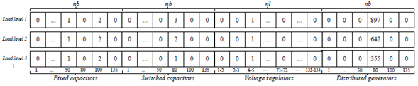
Figure 2: Proposed codification of candidate solutions.
In the case of fixed CAs (see first section of Fig. 2), a value other than zero indicates the number of standard capacitor units installed at bus i. This number is the same for all load levels under consideration. The first section of Figure 2 shows the representation of one fixed CA installed at bus 50, and two fixed CAs installed at bus 100. If the reactive power of each fixed CA unit is 300 kVAr, the codification represents injections of 300 kVAr and 600 kVAr (Qfx 50 =300 kVAr, Q fx 80 = 600 kVAr ), at buses 50 and 100, respectively. In the case of switched CAs (see second section of Fig. 2) a value other than 0 states that the number of standard capacitor units of switched capacitors can be different in each load level. According to Fig. 2 one switched capacitor is installed at bus 80. In this case, three load levels are considered (heavy, average, and light). If the reactive power of each switched CA unit is 300 kVAr, the proposed codification represents an injection of 900 kVAr for the heavy load level, 600 kVAr for the average load level, and 300 kVAr for the light load level.
The third section of Fig. 2 shows the codification of VRs. A value other than zero indicates the presence of a VR in branch ij. The value within the cell indicates the type of VR. This number is equal for all load levels. The Tap positions of the VRs are calculated according to Equation 17.
The fourth section of Fig. 2 shows the codification for DGs allocation. A value other than 0 in the vector indicates the presence of a DG unit installed at bus i. The value within the cell indicates the active power dispatch of such unit. For example, if the maximum active power of a DG is 1000 kW, and it is modeled with steps of 1 kW, the value in the cell, according to the proposed codification, can vary from 0 to 1000 steps. In the fourth section of Fig. 2 the value within the cell for heavy load level is 897, which indicates an active power injection of 897 kW. For the average and light load levels, the dispatch of such unit is 642kW and 355kW, respectively. A default power factor is used to calculate the reactive power injection of the DGs. The power supplied by them is a continuous variable. However, in the proposed codification, it is considered as discrete. This is not a drawback, since the proposed codification allows considering a finegrain discretization of this variable. For example, if the maximum active power of a given DG unit is 1000 kW with steps of 0,01 kW, the value in the corresponding cell varies from 0 to 100,000. If the value of the cell is 99,445 the active power dispatch is 994,45 kW.
Initial population
The GA requires an initial population that will be modified and improved over the next iterations. In the proposed methodology, the initial population is generated in a randomly controlled way. The number of individuals of the population is given by k ps . Since every individual of the population is represented by a matrix of four components (fixed and switched CAs, VRs, and DGs), each component is treated differently (see Fig. 2).
For fixed capacitors, a random number between 0 and ni fx,max is selected; for example, if this number is 3, then 3 buses are randomly selected to allocate fixed CAs. Then, a new random number between 0 and ni fx,max is selected for every bus in which the fixed capacitors are allocated in order to assign their respective sizes. The same procedure is executed for the case of switched capacitors. For voltage regulators, a random number between 0 and n vr,max is selected; for example, if this number is 2, then 2 branches are randomly selected to allocate VRs. After that, a new random number is selected for each voltage regulator to account for its type. Finally, regarding distributed generation, a random number between 0 and n dg,max is selected, and these DG units are randomly allocated in the network. After that, for each bus with DGs, a new number between 0 and ni dg,max is also selected to account for their respective capacity.
Objective function
In the proposed SGA, the objective function f o consists of a fitness (f) and a penalty (P) function, as indicated by Equation (33). The fitness function f corresponds to the annualized investment cost of the new elements installed in the network (CAs, VRs, and DGs) plus the cost of power losses (operational cost), and it is given by Equation (1). The second component of the objective function is a penalization applied to non-feasible solution candidates.

In this case, P is a penalty used for those individuals or solution candidates that violate constraints (11)-(16) and (20)-(28). If a given solution candidate does not violate these constraints, then the penalty is 0. P is given by Equation (34), where µ is the penalization factor, x
i
is the decision variable, and xi and
 represent its minimum and maximum limits.

Once the SGA generates a candidate solution (see Fig. 2) for the allocation of CAs, VRs, and/or DGs, the MINLP problem given by Equations (1)-(32) is turned into a nonlinear programming (NLP) problem. That is because the integer variables of the model are coded within the candidate solution of the SGA. The equivalent NLP problem is solved by means of a power flow. In this work, the backward/forward sweep power flow algorithm presented by Cheng and Shirmohammadi [41] was implemented. The power flow is computed to determine the stationary state of the network and determine voltages, currents, and power losses. Once the power flow has been calculated, constraints (11)-(16) and (20)-(28) are checked for feasibility. If any of these constraints are not held, the proposed candidate solution is considered unfeasible, and it is thus penalized as indicated by Equation (34).
Selection
In this step, a reduced number (k sr) of candidate solutions (or configurations) of the current population, are randomly chosen to compete with each other and choose one configuration known as parent. The configuration with the best objective function of the reduced list of configurations is chosen. This procedure is executed twice to select two parents to be used in the recombination mechanism.
Recombination
In this step, the two parents chosen in the selection process are considered. Recombination consists of exchanging information between two arrays (parents) to create two new arrays named offspring. In this case, the recombination is performed by type of element, since fixed or switched CAs cannot combine with VRs or DGs and vice-versa. Once the recombination process is complete, two new individuals are created. The next step consists on evaluating the objective function of each individual and selecting the best one to continue with the next steps of the SGA (mutation, local search, quality improvement, and acceptation criteria).
Mutation
The mutation process is the main mechanism that introduces diversity in the algorithm. In this paper, the mutation mechanism is used to add or remove a single unit of CAs, VRs, or DGs. This procedure considers account a mutation rate k mr corresponding to a pre-specified percentage of the total number of buses (in the case of allocating CAs or DGs) or branches (in the case of VRs) of the network.
Local search
In order to improve the quality of the current solution, a local search is performed to verify whether placing CAs or DGs at neighboring buses, or VRs in neighboring branches, improves the Fitness Function without introducing penalties. If this happens, the CA, VR, or DG is located at the new bus or branch; otherwise, it remains in its original location.
Quality improvement phase
Some elements (CAs, VRs, and/or DGs) of the proposed offspring may increase the total investment cost. Therefore, such elements must be removed from the solution. The unnecessary elements are those that can be discarded without modifying the penalty function (that is, without violating constraints) and represent a cost reduction. To eliminate such elements, they are sorted in descending order of their investment cost, and they are removed one by one. Every time an element is removed, a power flow is calculated to verify the fitness and penalty functions. At the end of this process, only the elements that do not modify the penalty function and worsen the fitness function are part of the solution proposal.
Acceptation criteria
In the proposed SGA, a new offspring is created in each iteration, so it is incorporated into the current population if its objective function z is better than the individual with the worst objective function in the current population. Furthermore, the new offspring must be different from all individuals of the current population; otherwise, the individual is discarded.
Stopping criteria
There are two stopping criteria for the SGA: the algorithm stops either when a maximum of iteration is reached, or when there has been a predetermined number of iterations (k of) without improvement of the objective function.
Tests and sesults
The IEEE 69-bus system was used to demonstrate the performance and robustness of the proposed approach. The system under study has a voltage level of 12,66 kV, and it must supply a total load of (3:802; 19 + j2:694,59) kVA. The distribution system data are available in [42]. The proposed methodology was implemented in the C++ programming language. All simulations were carried out on a personal computer with an Intel CoreTM i-7 3632MQ CPU @ 2.20 Ghz and 8GB of RAM memory.
The following values were considered in the model: k cp , k vr , k dg , and k e are equal to 1,0; Cf i f w and Cs isw are equal to US$ 1.000, Cf u f x and Cs usw are equal to US$ 900; Qi,d fx and Qi,t sw are equal to 300 kVAr, n fx,max; nsw,max are equal to 3; and ni fx,max, ni sw,max are equal to 4. Two types of VRs were considered with annualized costs of US$ 10.000 and US$20.000 and maximum current magnitudes of 200 A and 400 A, respectively. The values of n vr,max and n dg,max are equal to 2. The value of µ for the penalty function is equal to 106 for all tests. For comparative purposes, costs for fixed and switched CAs were considered to be the same. However, considering different costs for these elements is straightforward. It is worth noting that, 100 runs were initially performed for the tuning of the SGA parameters (selection and mutation rates as well as initial population size).
Description of tests
Thirteen tests were performed on this system. The first twelve tests were performed considering three load levels that were obtained with load factors of S 0 =1,0 (heavy), S 1 =0,8 (average), and S 2 =0,5 (light), with a duration of T 0 =1.000 h, T 1 =6.760 h and T 2 =1.000 h. The energy cost for all load levels was: c 0,1,2 =0,06 US$/kWh. The minimum voltage magnitude was considered to be 0,95 p.u. The last test was performed considering three load levels that were obtained by using load factors S 0 =1,25, S 1 =1,00, and S 2 =0,625, with a duration of T 0 =1.000 h, T 1 =6.760 h, and T 2 =1.000 h. The energy cost was c 0 =2,95 US$/kWh, c 1 =1,78 US$/kWh, and c 2 =0,7 US$/kWh; and the value of V min =0,9 p.u and V max =1,05 p.u. These values are the same as those considered in [36]. The control parameters of the SGA were as follows: the initial population size (k ps ) was 50, the rate by tournament (k sr ) was 3, the mutation rate (k mr ) is 3%, the maximum number of iterations (k Max ) was 10.000, and the maximum number of iterations without improvement of the objective function (incumbent) (k of ) was 1.000.
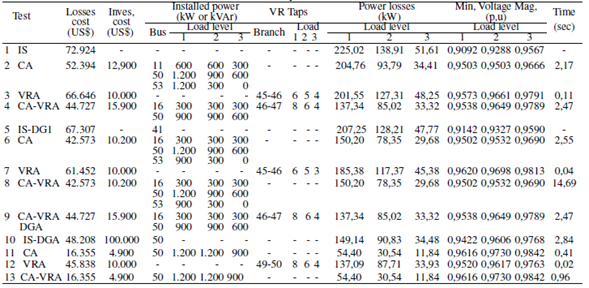
The thirteen tests performed in this system were labeled according to the elements to be optimally allocated (see first column of Table II). Test 1 corresponds to the initial state (IS) of the distribution network. Tests 2 and 3 (labeled as CA and VRA) correspond to the optimal allocation of capacitors and voltage regulators, respectively. Test 4 corresponds to the optimal allocation of capacitors and voltage regulators (CA-VRA). Test 5 was designed to compare the data with [1]. To this effect, a DG unit of 1.000 kW and a power factor of 0,95 was introduced in the initial system. Tests 6 to 8 were designed for the optimal allocation of capacitors (CA), voltage regulators (VRA), and both (CA-VRA), considering the previous DG unit introduced in test 5. In test 9, the optimal allocation of capacitors, voltage regulators and distributed generators (CA-VRA-DGA) was performed jointly. In Test 10, the optimal allocation of a single DG unit was performed (n dg,max =1), with a maximum active power of 1.000 kW and a power factor of 0,95 lagging. The total installation cost (Ci,g dg) was US$ 50.000. The active power was discretized in steps of 0,01 kW, each with an operation cost (Ci,g,d dg) of 0,5 US$ for all load levels. The solution of Test 10 was used as the initial state (IS-DGA) for Tests 11 to 13, which consider the optimal allocation of CA, VRA and CA-VRA, respectively.
Table II: Results summary of the IEEE 69-bus EDN
Result analysis
Table II shows a summary of the results. For comparative purposes, the initial state (IS) of the network is indicated in the first row of the table. In all tests, the minimum voltage magnitude of the network for all load levels was greater than the permitted minimum value of 0,95 p.u, and power losses were lower than those in the IS. In Test 2 (CA), three switched capacitors were allocated, with a total investment cost of US$ 65.294 (loss cost plus investment cost). In Test 3 (VRA), one voltage regulator of 200 A was allocated in branch 45-46, with a total investment cost of US$ 76.646. In Test 4 (CA-VRA), one fixed capacitor, one switched capacitor, and one voltage regulator of 200 A were allocated, with a total investment cost of US$ 60.627. In this case, the VR was allocated in branch 46-47. These first three tests showed better results than those reported in [1].
In Test 6 (CA), one fixed capacitor and two switched capacitors were allocated with a total investment cost of US$ 52.773. In this case, power losses dropped sharply when compared to the initial case (Test 5 IS-DG1). In Test 7 (VRA), one voltage regulator of 200 A was allocated in branch 45-46, with a total investment cost of US$ 71.452. In Test 8 (CA-VRA), the SGA did not allocate any VRs, and the algorithm found the same solution of Test 6. In Test 9 (CA-VRA-DGA), the solution did not include any DGs; the algorithm found the same solution of Test 4 due to the high investment cost of DGs. In Test 10 (IS-DGA), a single DG was allocated to bus 50. The active power injected for each load level is 1.000 kW for level 1 (heavy), 1.000 kW for level 2 (average), and 656,23 kW for level 3 (light). Note that the active power losses of this system drastically decrease due to the presence of the DG unit. In Test 11 (CA), one switched capacitor was allocated with a total investment cost of US$ 21.255. In Test 12 (VRA), one voltage regulator of 200 A was allocated in the branch 49-50, with a total investment cost of US$ 55.838. In Test 13 (CA-VRA), the SGA did not allocate VRs, and the algorithm found the same results of Test 11.
Fig. 3 depicts the voltage profile of the IEEE 69-bus EDN for the tests performed. Only 10 out of the 13 tests are illustrated since results of Tests 8, 9, and 13 are the same as those in Tests 6, 4, and 11, respectively (see Table II). It can be observed in Fig. 3 that differences in voltages are relatively small in nodes near the substation for all tests. However, for nodes further away from the substation, voltages are much more different for each test. It can be noted that, for the initial state (IS) and Test 5 (which is shown here for comparative purposes with [1]), the voltages in nodes 62 to 66 are below 0,92 p.u. Nonetheless, the sole inclusion of DG (Test 10) raised the voltage in these nodes over 0,94. As expected, the best voltage profile in these nodes was obtained when VRs were allocated in the network (Test 12).
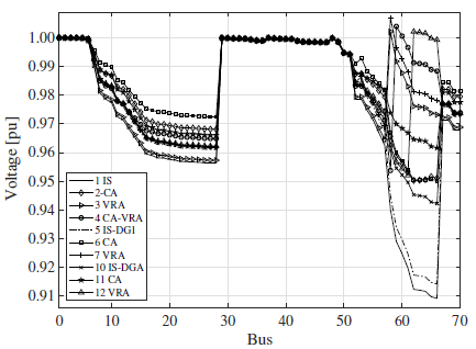
Figure 3: Voltage profile of the IEEE 69-bus EDN for maximum load level.
Figure 4 depicts power losses in different branches for Tests 1 to 4. For the sake of simplicity, only branches with power losses higher than 2 kW are illustrated. Also, only 4 tests are shown since power losses for other tests are similar to the ones already illustrated (see Table II). It can be seen that the optimal allocation of CAs and VRs reduces power losses, even though these elements do not provide active power to the EDN.
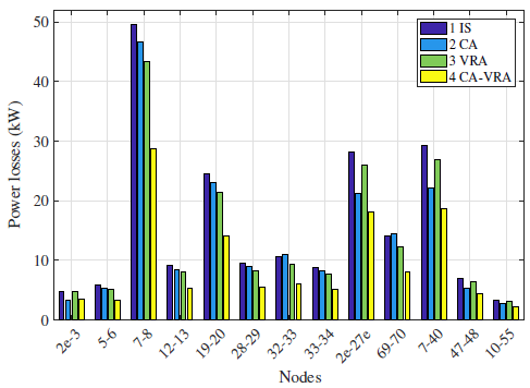
Figure 4: Power losses of the IEEE 69-bus EDN for maximum load level.
Result comparison
The results obtained with the SGA were compared with a hybrid method proposed in [2], a particle swarm optimization (PSO) method proposed in [36], and a Tabu Search metaheuristic proposed in [43]. This comparative study is shown in Table III. The bases of comparison are: 1) total investment cost, 2) loss cost, 3) investment cost of CAs, 4) optimal allocation of elements, 5) reactive power, 6) minimum voltage for each load level, and 7) capacitor type (fixed and/or switched). The results are sorted in descending order of their total investment cost. Note that the total investment cost found by the proposed SGA is lower than those reported in [43] and [36], and equal to the solution found in [2]. No further comparison is presented, since the aforementioned studies do not consider the joint allocation of CAs, VRs, and DGs, as proposed in this paper.
Table III: Result summary of the IEEE 69-bus EDN (comparative study)
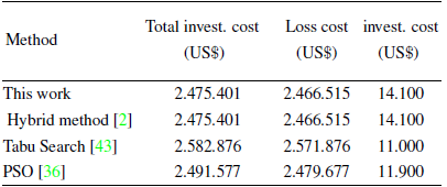
Table IV shows a comparative analysis of the investment proposals (cost and time) obtained in [1], and the ones found by the proposed SGA. In most of the tests, the proposed SGA was able to find better solutions than those reported in [1], and the computation time decreased drastically. For the test labeled as CA-VRADG1, the total investment cost of the SGA was slightly higher due to an increment in power losses resulting from the power flow. However, the solution found in these cases is the same as the one reported in [1] (the type of elements and location).
Table IV : Results and comparisons of investment proposals.
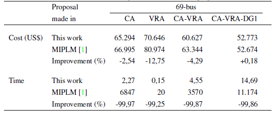
Fig. 5 illustrates the convergence of the SGA for different runs performed in Test 2. Note that the reproducibility of results is evident since the algorithm reached the same final value for all runs. Due to the diversity of solutions in the initial population, some runs took more iterations to converge. However, all of them reached the total cost (investment plus losses) reported by Test 2 in Table II.
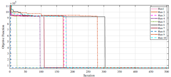
Figure 5: Convergence of the SGA for different runs in Test 2 in the IEEE-69-bus EDN.
Fig. 6 depicts the allocation of DGs, VRs, and CAs resulting from Tests 2, 4, 6, and 11 for illustrative purposes. Note that not all of the devices are considered to be simultaneously allocated. Further details regarding the results of these tests can be consulted in Table II.
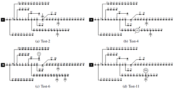
Figure 6: Optimal allocation of elements for different tests
Conclusions
This paper presented a mathematical model and a solution approach for the optimal allocation of capacitors, voltage regulators, and distributed generators in electric power distribution systems. The model can be used to optimize the allocation of all types of elements simultaneously, in pairs, or separately. The optimal placement of these elements was formulated as a MINLP problem and solved through a highly efficient metaheuristic. Furthermore, a full AC modeling to the network is considered, which provides more accurate solutions than linearization-based models.
Two stages were proposed to increase the efficiency of the proposed algorithm: local intensive search and quality improvement. Along with the fact that it was able to optimally allocate any of the devices previously mentioned, the main advantage of the proposed algorithm lies in its reduced computing time. This permits the use of the algorithm in real-size distribution systems. Also, the codification of DGs allows finding both the optimal sizing and the dispatch of DG units.
Several tests were designed for comparative purposes, considering different combination of elements to be allocated. Results on the IEEE 69-bus show the applicability and effectiveness of the proposed approach. The algorithm was able to find better solutions when compared with results previously reported in the specialized literature.
Acknowledgements
Acknowledgements
The authors gratefully acknowledge the support from the Colombia Científica program, within the framework of the Ecosistéma Científico (Contract No. FP44842- 218-2018).The authors also acknowledge the support of the State University of Londrina and Universidad Tecnológica de Pereira (UTP).
References
Nomenclature
Parameters
Variables
License
Copyright (c) 2020 Jesus Maria Lopez Lezama, Luis Alfonso Gallego Pareja, Oscar Gomez Carmona

This work is licensed under a Creative Commons Attribution-NonCommercial-ShareAlike 4.0 International License.
![]()
From the edition of the V23N3 of year 2018 forward, the Creative Commons License "Attribution-Non-Commercial - No Derivative Works " is changed to the following:
Attribution - Non-Commercial - Share the same: this license allows others to distribute, remix, retouch, and create from your work in a non-commercial way, as long as they give you credit and license their new creations under the same conditions.

2.jpg)