
DOI:
https://doi.org/10.14483/23448350.14827Publicado:
08/26/2019Número:
Vol. 36 Núm. 3 (2019): Septiembre-Diciembre 2019Sección:
Ciencia e ingenieríaFEA Analysis of coupled thermo-mechanical response of grey cast iron material used in brake discs
Análisis FEA de la respuesta termomecánica acoplada del material de fundición gris utilizado en los discos de freno
Palabras clave:
Brake disc, Pad, Contact, gray cast iron, Von Mises stress, contact pressure (en).Palabras clave:
Disco del freno, Almohadilla, Contacto, hierro fundido gris, El estrés de Von Mises, presión de contacto (es).Descargas
Referencias
Abu Bakar, A.R., Ouyang, H., Khai, L.C. and Abdullah, M.S.. (2010). Thermal analysis of a disc brake model considering a real brake pad surface and wear, Int. J. Vehicle Structures and Systems, 2(1), 20-27. https://doi.org/10.4273/ijvss.2.1.04
Adamowicz, A.; Grześ, P. (2012).Convective cooling of a disc brake during single braking, Acta Mechanica et Automatica, 6(2), 5-10.
Belhocine, A. and Ghazaly, N.M.(2016). Effects of Young’s Modulus on Disc Brake Squeal using Finite Element Analysis, International Journal of Acoustics and Vibration, 31(3), 292-300. https://doi.org/10.20855/ijav.2016.21.3423
Belhocine, A and Wan-Omar, W.Z.. (2017) .CFD modeling and computation of convective heat coefficient transfer of automotive disc brake rotors. Revista Científica. 29, 116-128. https://doi.org/10.14483/udistrital.jour.RC.2017.29.a1
Coudeyras, N. (2009). Non-linear analysis of multiple instabilities to the rubbing interfaces: application to the squealing of brake, PhD Thesis, Central school of Lyon-speciality: mechanics, December.
Gotowicki, P. F., Nigrelli, V., Mariotti, G. V., Aleksendric, D. and Duboka, C. (2005).Numerical and experimental analysis of a pegs-wing ventilated disk brake rotor with pads and cylinders, 10th EAEC Eur. Automot. Cong.–Paper EAEC05YUAS04–P5, June.
Ishak, M.R., Abu Bakar, A.R., Belhocine, A., Taib, J.M., Wan Omar, W.Z.(2018). Brake torque analysis of fully mechanical parking brake system: Theoretical and experimental approach, Ingenieria Investigacion y Tecnologia, 19(1) , 37-49. https://doi.org/10.22201/fi.25940732e.2018.19n1.004
Mackin, T.J., Noe, S.C., Ball, K.J., Bedell, B.C., Bim-Merle, D.P., Bingaman, M.C., Bomleny, D.M., Chemlir, G.J., Clayton, D.B. and Evans, H.A.(2002) .Thermal cracking in disc brakes. Engineering Failure Analysis, 9, 63−76. https://doi.org/10.1016/S1350-6307(00)00037-6
Oday, I. A. and Josef Schlattmann,J.(2016). Temperature analysis of a pin-on-disc tribology test using experimental and numerical approaches. Friction, 4(2), 135–143. https://doi.org/10.1007/s40544-016-0110-1
Oday, I. A. and Josef Schlattmann, J.(2016). Thermal behavior of friction clutch disc based on uniform pressure and uniform wear assumptions. Friction, 4(3), 228–237. https://doi.org/10.1007/s40544-016-0120-z
Oder, G., Reibenschuh, M., Lerher, T., Šraml, M., Šamec, B. and Potrč, I.(2009). Thermal and stress analysis of brake discs in railway vehicles. Advanced Engineering, 3(1), ISSN 1846-5900.
Palmer, E., Mishra, R. and Fieldhouse, J. D. (2009).An optimization study of a multiple row pin vented brake disc to promote brake cooling using computational fluid dynamics, Proc. Institution of Mech. Engineers, Part D, Journal of Automobile Engineering, 223(7), 865-875.
Reimpel, J. (1998).Braking Technology, Vogel Verlag, Würzburg.
Stephens, A. (2006).Aerodynamic Cooling of Automotive Disc Brakes, Master’s thesis, .School of Aerospace, Mechanical & Manufacturing Engineering, RMIT University, March.
Tang, J., Bryant, D. and Qi, H. (2014).Coupled CFD and FE thermal mechanical simulation of disc brake, Proc. Eurobrake Conference, Lille, France.
Cómo citar
APA
ACM
ACS
ABNT
Chicago
Harvard
IEEE
MLA
Turabian
Vancouver
Descargar cita
Recibido: de abril de 2019; Aceptado: de agosto de 2019
Resumen
En este trabajo, presentaremos el modelado numérico utilizando el software ANSYS adaptado para el método de elementos finitos, para seguir la evolución de las temperaturas globales para los dos tipos de discos de freno, disco lleno y disco ventilado durante un escenario de frenado. Además, la simulación numérica del análisis térmico transitorio y el estructural estático se realiza aquí secuencialmente con el método termoestructural acoplado. Un procedimiento numérico de cálculo se basa en pasos importantes, de modo que el análisis térmico de los CFDs está bien ilustrado en 3D, mostrando los efectos de la distribución del calor sobre el disco de freno. Este análisis de CFDs nos ayudará en el cálculo de los valores de los coeficientes térmicos (h) que se utilizarán en la evolución transitoria 3D de las temperaturas de los discos de freno. En esta simulación se seleccionaron tres materiales diferentes de discos de freno y se realizó un análisis comparativo de los resultados para obtener el que tuviera el mejor comportamiento térmico. Finalmente, la resolución del modelo termomecánico acoplado nos permite visualizar otros resultados importantes de esta investigación como son: las deformaciones y las tensiones equivalentes de Von Mises del disco, así como la presión de contacto de las pastillas de freno. Tras nuestro análisis y los resultados que obtenemos de él, obtenemos varias conclusiones. La elección nos permitirá ofrecer el diseño más adecuado del rotor de freno para asegurar y garantizar el buen rendimiento de frenado de los vehículos.
Palabras clave:
disco del freno, almohadilla, contacto, hierro fundido gris, el estrés de Von Mises, presión de contacto.Abstract
In this work, we will present numerical modeling using the ANSYS software adapted for finite element method, to follow the evolution of the global temperatures for the two types of brake discs, full and ventilated disc during a braking scenario. Also, the numerical simulation of the transient thermal analysis and the static structural one is performed here sequentially with the coupled thermo-structural method. A numerical procedure of calculation relies on important steps such that the CFD thermal analysis is well illustrated in 3D, showing the effects of heat distribution over the brake disc. This CFD analysis will help us in the calculation of the values of the thermal coefficients (h) that will be exploited in the 3D transient evolution of the brake disc temperatures. Three different brake disc materials were selected in this simulation and a comparative analysis of the results was conducted in order to derive the one with the best thermal behavior. Finally, the resolution of the coupled thermomechanical model allows us to visualize other important results of this research such as; the deformations, and the equivalent stresses of Von Mises of the disc, as well as the contact pressure of the brake pads. Following our analysis and the results we draw from it, we derive several conclusions. The choice will allow us to deliver the best suitable design of the brake rotor to ensure and guarantee the good braking performance of vehicles.
Keywords:
brake disc, pad, contact, gray cast iron,Von Mises stress, contact pressure.Introduction
The automobile is a complex integration of electronics and mechanical parts. One of the major components is the braking system which is limited due to its shortcomings. The specific air flow surrounding the brake rotor depends on the thermal performance of the disc brake and hence, the aerodynamics is an important in the region of brake components (Belhocine and Wan-Omar, 2017). It is obvious, therefore, that the calculation of the heat transfer coefficient (h) in simulation and numerical modeling is very serious. However, this coefficient is very difficult to evaluate; because of the complexity of friction phenomenon in the braking phase of automobiles. Abdullah and Schlattmann (2016) developed fully coupled thermal-mechanical approach to find the solution of thermoelastic problem of the sliding systems in dry condition using a numerical approach based on the finite element technique. Abdullah and Schlattmann (2016) conducted a numerical study using developed axisymmetric models to simulate the frictional part of dry clutch system. In the work done by Tang et al. (2014), and in the context of improving the accuracy of coupled computation techniques (CFD and FE), a modeling of the transient thermal transfer of brake disc was presented by the authors. Adamowicz and Grzes (2012) used the finite element technique (FEM) in their study to clarify the effect of the convection transfer coefficient (h) around a full disc during its heat dissipation phase. Ishak et al. (2018) developed a one dimensional model of leading-trailing drum-type parking brake and then verified with experiments test bench. Belhocine and Nouby (2016) developed a finite element model of the whole disc brake assembly and validated by using experimental modal analysis.
The main purpose of this scientific contribution is to present a numerical simulation during a stop braking step in order to visualize the thermomechaical behavior of the automobile brake discs while considering the generation of an initial heat flow generated by friction between both parts in dry contact (the rotor and the brake pads). We will focus first, on the actual evaluation of the values of time-dependent heat transfer coefficients (HTC), by adopting the ANSYS CFX code to which they will be used in the prediction of the transient temperatures of brake discs while seeing the performance of three gray cast irons. Our general concern here is to identify the disc material that is more tolerant to temperature increases. Thus, comparative results on the temperatures of the two discs allowed us to get the best cooling style that is used in the prototype of manufacture of automotive brake discs. These are then compared with experimental results obtained from literatures that measured ventilated discs surface temperatures to validate the accuracy of the results from this simulation model. This simulation will allow us to visualize some important results such as, the global deformations and the Von Mises stress of the model (disc-pads), the field of contact pressure of the inner pads as well as, the influence of the brake pad groove and the mode of loading exerted by the piston on the stresses established on the structure. These simulation results are satisfactorily verified by comparing with similar literature result. Thus, this study provides effective reference for design and engineering application of the brake disc and brake pad. The obtained results by this simulation can be considered as a guideline to the automotive braking with the thermal gradients and the damage phenomena of damage observed in disc brakes.
Brake disc kinds
We know in the field of the automobile, two kinds of brake discs; full discs and ventilated ones. Full discs usually have a crown attached to the bowl of the disc which is nailed to the wheel of the vehicle (figure1a). Ventilated brake discs are modern discs of complex shape used in our time when they are equipped at the front axles of vehicles by constituting two so-called broken crowns which are separated by fins (figure 1b).
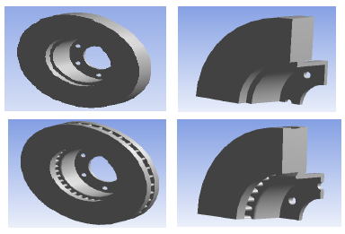
Figure 1: CAD model of discs brakes: (a) Full disc (b) Ventilated disc.
CFD modelling and analysis with ANSYS CFX
Governing equations
In this analysis, we will present a simplified model and simulation of a surface flux of heat in the brake disc caused by friction while using ANSYS CFX software. The model we found here in this study is similar to that developed by Palmer et al. (2009).
Continuity Equation:
The conservation equation of mass in the case of compressible and incompressible fluids is defined as follows
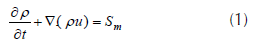
where Sm is the mass added to the continuous phase from the dispersed second phase.
Momentum (Navier Stokes) Equations:
In the inertial frame, the general equation the conservation of momentum is given by the form:
The left term of equation (2) can be reduced to the form below by using the rotating reference frame (RRF) technique in the case of a rotating brake disc and in absolute speeds.

where the stress tensor is of the form:
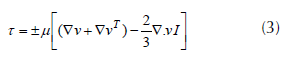
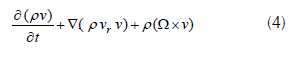
where, Ω and vr are respectively the angular velocity and the absolute velocity, the continuity equation used in the analysis (RRF) is expressed;
Heat flux entering the disc
The general formula for calculating the initial flux entering the automotive brake disc can be expressed as follows (Reimpel, 1998):
where g is the acceleration of gravity (9.81) [ms-2], a is the deceleration of the automobile [ms-2], z = a/g is the braking efficiency. Given the complexity of the phenomenon treated, we will assume that the thermal flux entering the rotor and the brake pads replace the effect of dry friction between the two bodies in contact, as shown in figure 2.
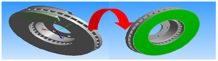
Figure 2: Heat flux from braking friction.
k-ε Turbulent Model
The turbulence model (k-ε) is the most widely used model in the field of analysis (CFD) as a numerical simulation of the average flow characteristics in the turbulent flow regime. It is a two-equation model that gives a general description of turbulence using two transport equations (PDE) one for turbulent kinetic energy (k) and the other for dissipation (ε). For current models, the model provides a good agreement for accuracy and virility.
CFD analysis with ANSYS CFX
Various external and internal faces of the two structures, full and ventilated disc that were derived from the code ANSYS ICEM CFD are shown in figures 3 and 4.
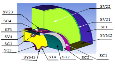
Figure 3: Quarter of full disc showing the assignment of face names in the simulation.
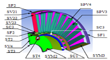
Figure 4: Quarter of the ventilated disc showing the assignment of face names.
The mesh is realized here in linear tetrahedral elements with 179798 elements and 30717 nodes (figure 5). The ANSYS-CFX code solves the CFD aerodynamic model of the brake disc while basing on the transitory type of the problem whose all boundary conditions were injected in both domains (solid and fluid).
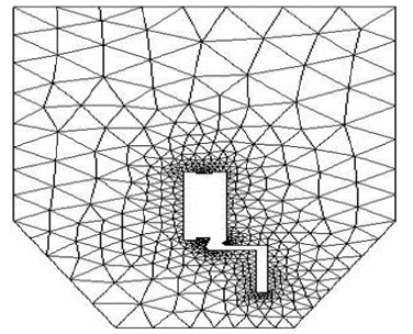
Figure 5: Wall meshes for the CFD simulation
Boundary conditions and computational details
In this calculation, given the symmetry of the disc and the periodic repetition due to rotation of the rotor, the entire model of the disc is reduced and simplified to only a quarter to reduce the simulation calculation time, that is why the conditions boundary, periodic and symmetrical have been so designated.
In order to easily model the rotational aspect of the automobile brake disc in the environment, the output and inlet edges of the fluid model are maintained in atmospheric temperature and pressure. The surrounding air temperature of the disc is set at 20 °C using a rotating reference frame for the management of the brake disc movement. Symmetrical boundary conditions are also used to produce shear walls with zero shears. The CFD model developed in ANSYS CFX used in the search for exchange coefficient values (h) is well shown in figure 6.
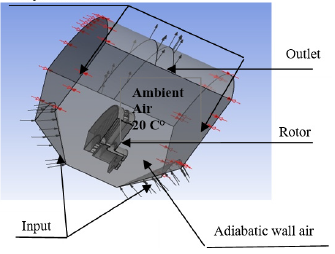
Figure 6: CFD model of ventilated disc brake.
Finite-Element Modelling
Modelling Assumptions
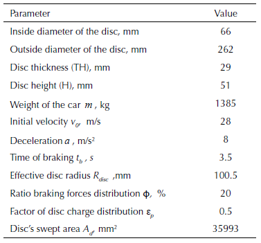
The standard dimensions of the full and ventilated brake disc are identical in this numerical simulation to ensure a better comparison of the results. Table 1 lists all the physical parameters and the geometric dimensions of the brake disc used in numerical calculations.
Table 1: Design parameters of brake disc.
The material of the brake disc that we have opted for in this simulation having a carbonaceous assembly is gray cast iron (FG15) (Gotowicki et al., 2005), having excellent tribo-thermomechanical properties. We consider that brake pads having a material characterized by purely isotropic elastic behavior whose properties of the two parts involved are explained in table 2 below.
Table 2: Properties of the disc and pad.
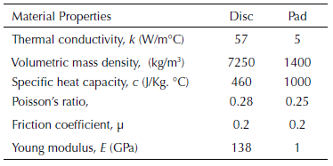
Mesh of disc brake model
The final mesh therefore comprises 172103 nodes and 114421 elements for the full disc, and 154679 nodes and 94117 elements for the ventilated disc, as it is represented in figure 7.
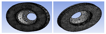
Figure 7: Disc brake mesh model: (a) Full disc, (b) Ventilated disc.
Boundary conditions applied to the model
The parameters of the initial, minimum and maximum and final time increment for the simulation shall be inserted at the values (0.25 s, 0.125 s, 0.5 s, 45 s) respectively, maintaining the initial temperature of the disc at 20 °C. The thermophysical characteristics of the 3 types of gray cast iron brake discs (FG 15, FG20, and FG25AL) are introduced in the simulation. The values of the convection exchange coefficient (h) for each face of the brake disc must be imported from the CFX analysis results and must be used in the ANSYS Workbench Multiphysics analysis. These will be shown in the following in the graphs of figure 13 (a)-(b). The heat flux imposed on the lateral surfaces corresponds to their values resulting from the CFX analysis.
Experimental setup
The numerical results of the thermal simulation obtained in this work using ANSYS are validated using the results of the work of Stephens (2006), which was an experimental investigation on temperature distribution of ventilated brake rotor disc.
Temperature measuring with embedded thermocouple
The temperature measurement was conducted using Cu thermocouples integrated in the disc brake rotors according to VDA285-1, which became accredited until the year 1996, at the mean friction radius as shown in figure 8(a). The temperature pot-side was measured also by a Cu-embedded thermocouple as shown in figure 8(b). The thermocouples have a cylindrical shape in this case with the sizes Ø = 3mm and h = 3 mm as in figure 8(c). The connecting wires were insulated on the brake-rotor-side and were connected to the signal amplifier.
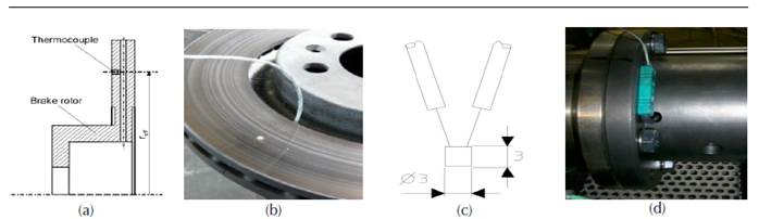
Figure 8: Temperature measuring with embedded thermocouple as per VDA285-1.
Disc brake thermocouples
Thermocouples is the favored choice for testers due to their cost, ease of use and availability, and are one of the most stable methods of measuring the temperature of disc brakes in vehicles with rubbing disc brakes. The device contains a K-type thermocouple, which is made using a silver wire welded to a flat piece of copper plate, and this plate is strongly supported against the rotating disc by a steel spring. An elementary diagram of the thermocouple is provided in figure 9.
Figure 9: Diagram of disc brake thermocouple.
Experimental procedure
The brake was connected to the external applicator and the right rear wheel of the racing vehicle was fitted in the brake test rig as shown in figure 10. The rubbing thermocouple was positioned to measure the temperature on the inner surface of the rotor. The thermocouple data were recorded in the PC via a Fluke data logger.
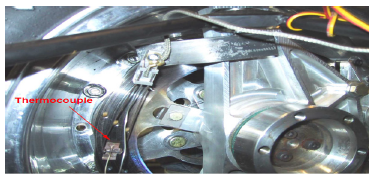
Figure 10: Close up view of thermocouple in position
The tests were performed by rotating the wheel at a constant speed approximately equal the vehicle speed of 108 km/h. A progressive braking load was applied and the temperatures were recorded at very short intervals of 0.01 seconds. The method started with the disc heating up to a temperature of about 345 °C, at which point the braking load was released. The recording continued there on until the temperature of the rotor dropped to about 200 °C. The results of the thermocouple readings were obtained directly from the PC in temperature scale.
Results and discussion of CFD analysis
Steady State Cases
The results obtained from the distribution of the wall heat transfer coefficient of the two of the discs in stationary state are illustrated in the figures 11 and 12.
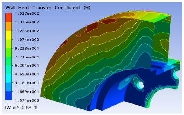
Figure 11: Values of heat transfer coefficient at the wall of fulldisc with material FG15 in steady state thermal analysis.
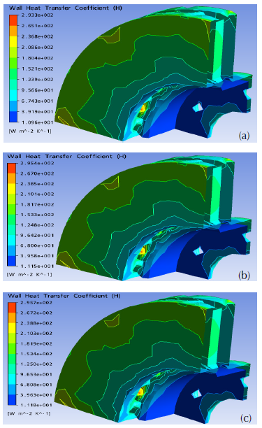
Figure 12: Values of heat transfer coefficient at the wall of the ventilated discs with materials (a) FG25 AL, (b) FG20 and (c) FG15 in steady state thermal analysis.
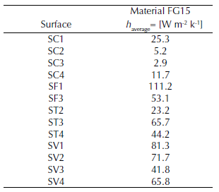
Table 3 lists the average heat transfer coefficients of the named surfaces in the CFD model of the full brake disc made of the material FG15.
Table 3: Values of the wall heat transfer coefficients of different surfaces in the steady state case for a full disc with material FG15.
The distribution of the heat transfer coefficient to the wall (h) according to the three types of brake disc materials is well represented in figures 11-12. It is observed that the variation of (h) in the brake disc does not subordinate to the material and that this one is not the same one found in the specialized literature.
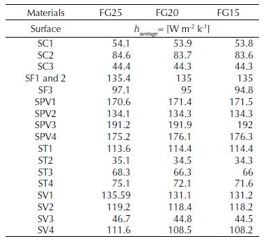
From the maximum and minimum values of the various areas of the ventilated brake disc, the average values of the heat transfer coefficient can be taken from the wall (h). These harvested data are grouped together in table 4. From the observation, it can be seen that there is no significant variation in this coefficient (h) when changing the material of the brake disc. Contrary to what we have seen, the heat transfer coefficient values at the wall are much more influenced by the ventilation system of the brake disc for the same material (FG15).
Table 4: Values of the wall heat transfer coefficients of different surfaces in steady state case for ventilated discs with materials FG25 AL, FG20 and FG15.
Transient Cases
Evaluation of the heat exchange coefficient (h)
Figure 13(a)-(b) show the evolution of the heat transfer coefficient (h) at each surface of the full and ventilated disc, as a function of time. We will use these two graphs later to predict the three-dimensional distribution of the two brake discs. It can be said that the values of the convective heat exchange coefficient (h) vary according to the geometric design of the disc, whether it is full or ventilated and, it is quite rational that the aeration generates the decrease of the maximum temperatures at the walls.
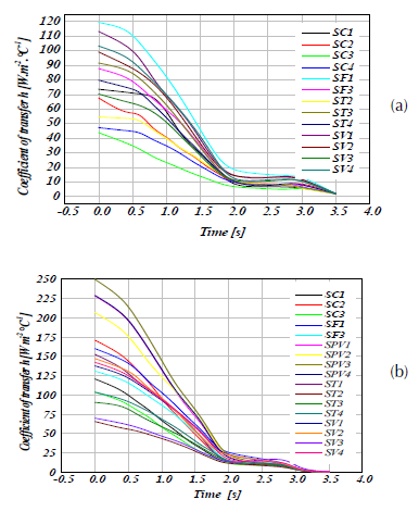
Figure 13: Heat transfer coefficient (h) versus time at different disc surfaces at material FG15 in transient thermal case for (a) full disc faces, and (b) ventilated disc.
Results and discussion of FEM analysis
Model validation against experimental data
The analysis in this work is compared to available literatures to ensure the reliability of the results. Figure 14 shows the time variation of the observed disc temperature against the values of (Stephens, 2006). Figure 14 shows that the temperature results from both the thermocouple and the finite element software ANSYS 11.0 of the ventilated disc brake made of material FG15 are very similar. It is believed that the response of the thermocouple is a little slower in cooling than heating due to residual heat in its rubbing components. But the variations is so small as shown in the figure, such that it was decided that the level of accuracy of rubbing type thermocouples used in the experimental stages of this research is acceptable. It can also be concluded that the transient thermal simulation of the ventilated disc, performed by the finite element method, gives us a good correlation with the thermocouple measurements.
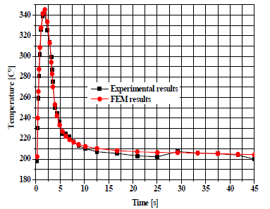
Figure 14: Validation of the FEM model against experiments by Stephens (2006).
Results of the disc temperature
In order to perform a multi-step analysis, in order to simulate the thermal behavior of a full, ventilated automotive brake disc, we used the ANSYS Workbench 11.0 software under a transient thermal analysis. The internal and external surfaces of the brake disc are biased to a symmetrical heat flow during mutual sliding of the disc in a rotational movement around the fixed brake pads. During this cyclic mechanism, we distinguish the alternation of two thermal phenomena associated with convection; it is in this case, the heating and cooling of the brake disc.
The transient thermal analysis of the two discs, full and ventilated brake discs were performed using finite element (FE) software. The calculation does not last very long, which is a positive point. The results of the temperature distribution (3D) for the three materials namely; the gray cast iron FG25AL, FG20 and FG15 are provided in figure 15. It should be understood that the material having a lower thermal conductivity thus generates important thermal gradients and consequently an increase in the surface temperature of the brake disc. To make the choice of material and to know if it is profitable, we tested the one that cools better, it is necessary to remember that one wants to have a material which does not preserve the heat. From the results provided by this simulation, it can be seen that the ventilated discs made of the materials FG20 and FG25AL, respectively, will have temperatures reaching 351.5 and 380.2 °C, which in turn, are greater than that of the ventilated disc of material FG15 having a maximum temperature of 345.4 °C as indicated in figure 16. It can thus be concluded that the most suitable material in this case for the brake discs is the gray cast iron FG15 which presents the better thermal performance.
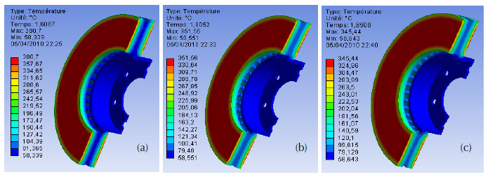
Figure 15: Temperature plot of ventilated discs for three materials gray cast iron (a) FG25 AL, (b) FG20, and (c) FG15.

Figure 16: Temperature plot on disc brake of the same material (FG15) (a) Full disc, (b) Ventilated disc.
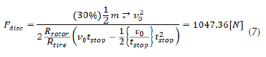
Figure 17 shows the temperature of the brake disc at time t = 1.8 s reaching a maximum value of 401.5 °C, and after that, it decreases exponentially at 4.9 s until it reaches braking cycle termination at instant, t = 45 s. The forced convection step is well designated in the temporary interval between the instant 0 s and 3.5 s, as shown in figure 17. On the other hand, the natural or free convection is quite marked after the duration of the forced convection arriving at the end of braking time, which is the total time of the simulation (t = 45 s). It can be seen from the graphs that the temperature of the full brake disc exceeds that of the ventilated disc with a difference of 60 °C. Finally, we can draw the conclusion that the ventilated brake disc allows us to provide better cooling therefore, better endurance and gives us an ability to dissipate more heat for braking efficiency.
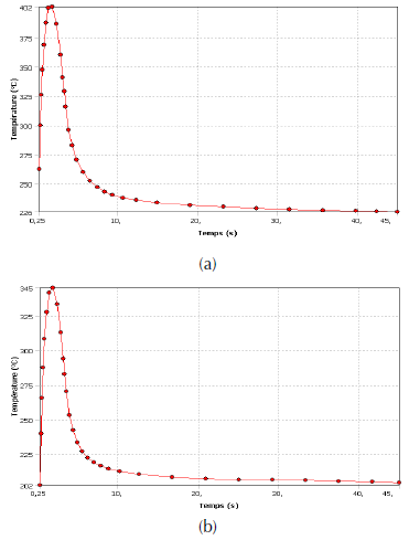
Figure 17: Disc temperature versus time for (a) full disc and (b) ventilated disc, for material gray cast iron FG15.
Coupled thermo-mechanical analysis
Calculation of hydraulic pressure
In order to proceed with the preliminary mechanical calculation, we will determine the constant value of the hydraulic pressure exerted by the piston on the inner brake pad. For this, we will assume that the rate of 60 % of the braking forces is maintained both front brake discs, giving a percentage of 30 % for each rotor (Mackin et al., 2002).
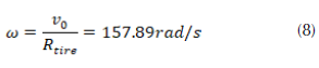
Using the above calculations, the value of the hydraulic pressure P is obtained from the following form (Oder et al., 2009)
Where , μ is the friction coefficient,A C is the surface of the brake pad in contact with the brake disc.
FE model and boundary conditions
The limit conditions applied to the model result from the assumptions and model choices presented above. Figure 18 (a) and (b) shows the boundary conditions imposed on an FE model, consisting of a brake disc and two brake pads in dry contact in the case, of pressure exerted on one side of the pad and that of a double pressure on both sides of the pad.
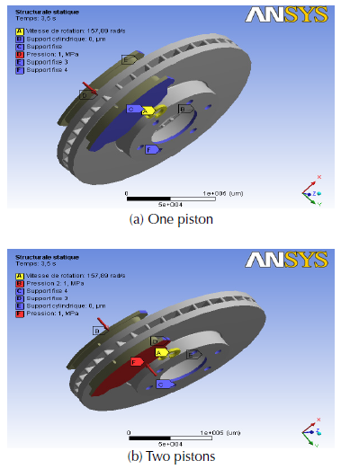
Figure 18: Loading conditions for disc brake assembly.
As we have done a thermal analysis, the conditions to be taken into account are those which will influence the thermal phenomena such as the ambient temperature which is the initial temperature of disc 20 ° C, the thermal flow and that of convection imposed on all the surfaces of the brake disc while for the two brake pads (Abu Bakar et al., 2010), a convection heat exchange coefficient (h) of value 5 W / m2. ° C is applied on their outer surfaces on both sides (figure 19).

Figure 19: Thermal boundary condition applied to the model.
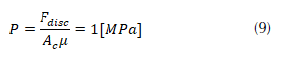
For structural boundary conditions, we know that the brake disc is fixed to the mounting holes thus requiring fixed support on these holes taking into account its rotational speed (Coudeyras, 2009). ω = 157.89 rad / sec. The internal disc diameter is sustained at fixed support for both radial directions while the tangential direction is left free in this simulation.
The structural boundary conditions applied to pads are also introduced. We imposed pressure of 1 MPa on the piston pad while maintaining fixed support on the finger pad while on the contact surface; the pad is assembled on its edges at the perpendicular plane. The friction between the two disc-brake pad parts is defined by a coefficient equal to 0.2.
Geometry and mesh
Three-dimensional mesh of ventilated disc was developed under the ANSYS software (figure 20). The total number of nodes is 185901 while the total number of elements is 113367.
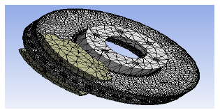
Figure 20: Meshed model of disc brake assembly.
Thermal distortion
Figure 21 shows the maps of the total deformation of the whole model (disc-brake pads) evaluated at times t = 1.7271s, 3.5s, 30s and 45s. According to this figure, the maximum total deformation recorded at time t = 3.5 s is of the order of 284.55 μm, where it coincides with the braking moment. It is obvious that a strong distribution amplifies with time as well on the tracks of friction of the disc and its outer ring that its fins of cooling. Indeed, at the beginning of the braking, relatively homogeneous, relatively homogeneous, hot bands appear on the friction tracks of the disc. During braking, this hot strip with hot spots gradually migrates to the inner radius. Hot spots intensify to form stationary macroscopic hot spots at the inner radius. At the end of the braking, the intensity decreases and the surface gradients homogenize. The migration of the locations is explained by the difference in expansion between the track of the disc and its rear face, leading to an “umbrella” deformed disc during warm-up. Deformation of the structure therefore, has a preponderant role in the migration of thermal locations.
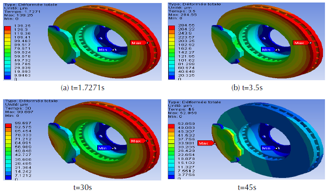
Figure 21: Total deformation of disc-pad model.
Von Mises stress distribution
The model provides access to Von Mises stress distribution mapping at the start of braking (figure 22) and after cooling the sector to ambient temperature. The distribution is well noted here in an order ranging from 0 to 495.56 MPa. The great value recorded during this modeling in thermomechanical coupling is very significant when compared to mechanical dry contact analysis under the same braking conditions. According to the established conclusion, the Von Mises stresses are maximum in the outer band at the level of the brake disc bowl at the instant 3.5 s, corresponding to the moment when the thermal gradient in the thickness of the track is the most important. Indeed, the brake disc is fixed to the hub by bolts in order to prevent its movement and as soon as it starts to rotate, torsion and shear stresses have just been produced at the level of its bowl which generates automatically stress concentrations around its fixing holes. The disc bowl thus risks a mechanical rupture under repetitions of these undesirable effects during the braking process. The general evolution of the stresses in the disc during the braking-cooling cycle is in agreement with the phenomena described in the previous literature searches.
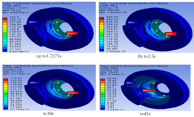
Figure 22: Von Mises equivalent stress obtained step by step
Contact pressure distribution
Figure 23 shows the mapping of the contact pressure at the friction interface between the internal brake pads and the brake disc with various simulation times. In these, the maximum contact pressures evaluated are of the order of 3.3477 MPa at the instant when the rotational speed is zero t = 3.5 s. It can also be seen that this maximum value is in the leading edges of the pads towards the trailing edge by friction. Moreover, the distribution of the contact pressure is quite symmetrical with respect to the groove of the brake pads. In the thermomechanical coupling that we carried out here, it is clear that the contact pressures are not negligible and can reach locally very high values, of the order of GPa. The plastic flow observed in the sliding direction attests well to the severity of the friction forces, so very high contact pressure.
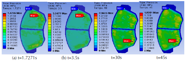
Figure 23: Contact pressure distribution in the inner pad.
Von Mises stress at the inner pad
In order to study the influence of the groove of the brake pads as well as loading modes applied to the pistons (single-pressure and double-pressure). We solve the model and ask for the equivalent Von Mises stress of three different designs. Brake pads in this case, brake pad with center groove subject to a single double piston. We obtain the following visuals that are grouped in figures 24(a) to 24 (c). It can be seen that almost all the contact pads of the brake pads are dressed in a dark blue color meaning low stresses at the beginning of the braking moment (t = 1.7 s). Nevertheless, from the moment of the end of braking t = 45 s, the scale of the constraints of Von Mises becomes more important whose vision of the colors becomes practically blue ocean whose distribution is well noticed on the three conceptions. It can be concluded that the existence of a groove in a brake pad and the presence of a mechanical double piston loading have a positive influence on the distribution of brake pad stresses.
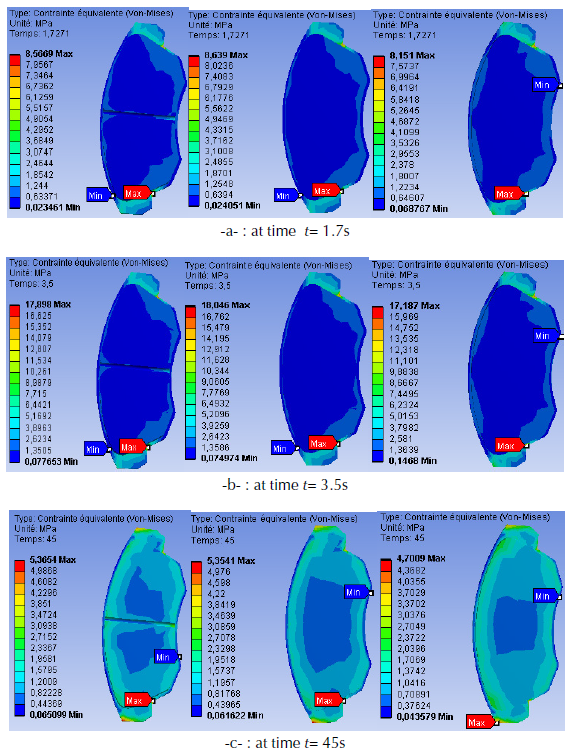
Figure 24: Distribution of Von Mises stress at different braking time: Single piston with pad center-groove (left), Single piston without groove (center) and Double piston without pad groove (right).
Conclusion
In the transport sector, braking is a major problem. It is a question of obtaining on this safety equipment a systematic reliability with an acceptable cost, whereas the phenomena which are attached to it are complex. In general, from the point of view of the thermal, the braking system is considered to be composed of only three elements: the disc in motion at variable speed, on which are rubbed the two pads which are subjected to pressure evolving over time. The phenomenon of induced friction will generate a dissipation of thermal power at the interface and will cause a sharp increase in temperature may deteriorate the equipment. The temperature level reached will be directly related to the way in which the heat is transferred into its immediate environment, that is to say the disc and the two pads. In this paper, we presented a complex modeling of convection-driven brake discs in order to predict the heat transfer coefficients (h) during the aerodynamic conditions of the braking stage by using the software adapted in elements. ANSYS CFX finishes. Moreover the important results resulting from this numerical computation were used to study the transient thermal scenario during the braking and which was executed on the two full and ventilated brake discs to which one visualized the temperature reached thanks to the software ANSYS Workbench. The results were also validated using the temperature-time profile from both the simulated and experimental results, in which the two results were found to be in good agreement. The literatures for ventilated brake disc with gray cast iron FG15 also gives a good agreement with results from literatures. In this research, we simulated the disc brake-pad assembly model by employing a coupled thermomechanical approach of which some useful results have been drawn from this analysis. However, it seems to us that several thermomechanical turns can and should be visited in more detail in the topic of braking, essentially for a more quantitative estimation of damage in a life expectancy approach, which are defined in perspective. Additional thermomechanical speculations could be taken into consideration to better comment on the effect of migration of thermal locations.
References
Licencia
Derechos de autor 2019 Ali Belhocine, Asif Afzal

Esta obra está bajo una licencia internacional Creative Commons Atribución-NoComercial-CompartirIgual 4.0.
El (los) autor(es) al enviar su artículo a la Revista Científica certifica que su manuscrito no ha sido, ni será presentado ni publicado en ninguna otra revista científica.
Dentro de las políticas editoriales establecidas para la Revista Científica en ninguna etapa del proceso editorial se establecen costos, el envío de artículos, la edición, publicación y posterior descarga de los contenidos es de manera gratuita dado que la revista es una publicación académica sin ánimo de lucro.

