DOI:
https://doi.org/10.14483/23448393.19174Published:
2023-04-29Issue:
Vol. 28 No. 2 (2023): May-AugustSection:
Mechanical EngineeringEstudio numérico del comportamiento estructural del perfil del álabe de un rotor tipo Savonius implementando una geometría multielemento
Numerical Study on the Structural Behavior of the Blade Profile of a Savonius-Type Rotor while Implementing a Multiblade Geometry
Keywords:
CFD, multiblade, multiphysics, Savonius rotor, wind energy (en).Keywords:
CFD, energía eólica, multielemento, multifísica, rotor Savonius (es).Downloads
References
A. A. Mohammed, H. M. Ouakad, A. Z. Sahin, and H. Bahaidarah, “Vertical axis wind turbine aerodynamics: Summary and review of momentum models,” J. Energy Resour. Technol., vol. 141, no. 5, 2019. https://doi.org/10.1115/1.4042643 DOI: https://doi.org/10.1115/1.4042643
S. Eriksson, H. Bernhoff, and M. Leijon, “Evaluation of different turbine concepts for wind power,” Renew. Sust. Energ. Rev., vol. 12, no. 5, pp. 1419–1434, 2008. https://doi.org/10.1016/j.rser.2006.05.017 DOI: https://doi.org/10.1016/j.rser.2006.05.017
K. Ibrahim, V. S. Djanali, and N. Ikhwan, “Numerical study of bach-bladed savonius wind turbine with varying blade shape factor,” JMES Int. J. Mech. Sci., vol. 4, no. 2, pp. 12–21, 2020. http://dx.doi.org/10.12962/j25807471.v4i2.7839 DOI: https://doi.org/10.12962/j25807471.v4i2.7839
B. Zhang, B. Song, Z. Mao, and W. Tian, “A novel wake energy reuse method to optimize the layout for Savonius-type vertical axis wind turbines,” Energy, vol. 121, pp. 341–355, 2017. https://doi.org/10.1016/j.energy.2017.01.004 DOI: https://doi.org/10.1016/j.energy.2017.01.004
J. T. Hansen, M. Mahak, and I. Tzanakis, “Numerical modelling and optimization of vertical axis wind turbine pairs: A scale up approach,” Renew. Energ., vol. 171, pp. 1371–1381, 2021. https://doi.org/10.1016/j.renene.2021.03.001 DOI: https://doi.org/10.1016/j.renene.2021.03.001
S. J. Savonius, “The S-rotor and its applications,” Mech Eng., vol. 53, no. 5, pp. 333–338, 1931.
L. Chen, J. Chen, and Z. Zhang, “Review of the Savonius rotor’s blade profile and its performance,” Renew. Sust. Energ. Rev., vol. 10, no. 1, p. 013306, 2018. https://doi.org/10.1063/1.5012024 DOI: https://doi.org/10.1063/1.5012024
K. Golecha, M. Kamoji, S. Kedare, and S. Prabhu, “Review on Savonius rotor for harnessing wind energy,” Wind. Eng., vol. 36, no. 6, pp. 605–645, 2012. https://doi.org/10.1260/0309-524X.36.6.605 DOI: https://doi.org/10.1260/0309-524X.36.6.605
A. Kumar and R. P. Saini, “Performance parameters of Savonius type hydrokinetic turbine: A review,” Renew. Sust. Energ. Rev., vol. 64, pp. 289–310, 2016. https://doi.org/10.1016/j.rser.2016.06.005 DOI: https://doi.org/10.1016/j.rser.2016.06.005
S. J. Savonius, “Vertical axis wind turbine,” 1929. US Patent 1,697,574.
H. H. Al-Kayiem, B. A. Bhayo, and M. Assadi, “Comparative critique on the design parameters and their effect on the performance of S-rotors,” Renew. Energ., vol. 99, pp. 1306–1317, 2016. https://doi.org/10.1016/j.renene.2016.07.015 DOI: https://doi.org/10.1016/j.renene.2016.07.015
Y. Cengel and J. Cimbala, Fluid Mechanics: Fundamentals and Applications, Fourth Edition. New York: McGraw-Hill Education, 2018.
L. A. Gallo, E. L. Chica, E. G. Flórez, and F. A. Obando, “Numerical and experimental study of the blade profile of a Savonius type rotor implementing a multi-blade geometry,” Appl. Sci., vol. 11, no. 22, p. 10580, 2021. https://doi.org/10.3390/app112210580 DOI: https://doi.org/10.3390/app112210580
L. A. Gallo, E. L. Chica, and E. G. Flórez, “Numerical optimization of the blade profile of a savonius type rotor using the response surface methodology,” Sustainability, vol. 14, no. 9, p. 5596, 2022. https://doi.org/10.3390/su14095596 DOI: https://doi.org/10.3390/su14095596
S. Roy and U. K. Saha, “Wind tunnel experiments of a newly developed two-bladed Savonius-style wind turbine,” Appl. Energy., vol. 137, pp. 117–125, 2015. https://doi.org/10.1016/j.apenergy.2014.10.022 DOI: https://doi.org/10.1016/j.apenergy.2014.10.022
J. V. Akwa, G. A. da Silva Júnior, and A. P. Petry, “Discussion on the verification of the overlap ratio influence on performance coefficients of a Savonius wind rotor using computational fluid dynamics,” Renew. Energ., vol. 38, no. 1, pp. 141–149, 2012. https://doi.org/10.1016/j.renene.2011.07.013 DOI: https://doi.org/10.1016/j.renene.2011.07.013
L. A. Gallo, E. L. Chica, and E. G. Flórez, “Estudio de desempeño de distintos perfiles de alabe de una turbina eólica para aprovechar vientos de baja velocidad,” Ing, vol. 27, no. 1, 2022. https://doi.org/10.14483/23448393.18127 DOI: https://doi.org/10.14483/23448393.18127
R. v. Mises, “Mechanik der festen k¨orper im plastisch-deformablen zustand,” Nachrichten von der Gesellschaft der Wissenschaften zu G¨ottin-gen, Mathematisch-Physikalische Klasse, vol. 1913, pp. 582–592, 1913.
R. Hill, “The mathematical theory of plasticity: Oxford University,” Press New York, 1950.
I. J. Levinson, Mechanics of materials. Prentice-Hall, 1963.
P. D. Barsanescu and A. M. Comanici, “von Mises hypothesis revised,” Acta Mechanica, vol. 228, no. 2, pp. 433–446, 2017. https://doi.org/10.1007/s00707-016-1706-2 DOI: https://doi.org/10.1007/s00707-016-1706-2
D. Best and N. I. Fisher, “Efficient simulation of the von Mises distribution,” J. R. Stat. Soc., C: Appl. Stat., vol. 28, no. 2, pp. 152–157, 1979. https://doi.org/10.2307/2346732 DOI: https://doi.org/10.2307/2346732
R. C. Hibbeler, Mecánica de materiales. Pearson México, 2017.
F. P. Beer, E. R. Johnston, J. T. DeWolf, and D. F. Mazurek, Mecánica de materiales. McGraw-Hill Education, 2021.
M. Kamoji, S. B. Kedare, and S. Prabhu, “Experimental investigations on single stage modified Savonius rotor,” Appl. Energy., vol. 86, no. 7-8, pp. 1064–1073, 2009. https://doi.org/10.1016/j.apenergy.2008.09.019 DOI: https://doi.org/10.1016/j.apenergy.2008.09.019
K. S. Jeon, J. I. Jeong, J.-K. Pan, and K.-W. Ryu, “Effects of end plates with various shapes and sizes on helical Savonius wind turbines,” Renew. Energ., vol. 79, pp. 167–176, 2015. https://doi.org/10.1016/j.renene.2014.11.035 DOI: https://doi.org/10.1016/j.renene.2014.11.035
S. Roy and U. K. Saha, “Review of experimental investigations into the design, performance and optimization of the Savonius rotor,” Proc. Inst. Mech. Eng. A: J. Power Energy, vol. 227, no. 4, pp. 528–542, 2013. https://doi.org/10.1177/0957650913480992 DOI: https://doi.org/10.1177/0957650913480992
T. Hayashi, Y. Li, and Y. Hara, “Wind tunnel tests on a different phase three-stage Savonius rotor,” JSME Int. J. Ser. B, vol. 48, no. 1, pp. 9–16, 2005. https://doi.org/10.1299/jsmeb.48.9 DOI: https://doi.org/10.1299/jsmeb.48.9
M. Braza, A. Bottaro, and M. Thompson, “Advances in fluid-structure interaction,” 2016. DOI: https://doi.org/10.1007/978-3-319-27386-0
Y. Bazilevs, K. Takizawa, and T. E. Tezduyar, Computational fluid-structure interaction: Methods and applications. John Wiley & Sons, 2013. DOI: https://doi.org/10.1002/9781118483565
J.-F. Sigrist, Fluid-structure interaction: An introduction to finite element coupling. John Wiley & Sons, 2015. DOI: https://doi.org/10.1002/9781118927762
H.-J. Bungartz, M. Mehl, and M. Sch¨afer, Fluid Structure Interaction II: Modelling, Simulation, Optimization, vol. 73. Springer Science & Business Media, 2010. DOI: https://doi.org/10.1007/978-3-642-14206-2
F. Axisa and J. Antunes, Modelling of mechanical systems: Fluid-structure interaction, vol. 3. Elsevier, 2006. DOI: https://doi.org/10.1016/S1874-7051(07)80003-X
G. P. Galdi and R. Rannacher, Fundamental trends in fluid-structure interaction, vol. 1. World Scientific, 2010. DOI: https://doi.org/10.1142/7675
G. Hou, J. Wang, and A. Layton, “Numerical methods for fluid-structure interaction: A review,” Commun. Comput. Phys., vol. 12, no. 2, pp. 337–377, 2012. https://doi.org/10.4208/cicp.291210.290411s DOI: https://doi.org/10.4208/cicp.291210.290411s
S. Bhakade, S. Kumbhar, Y. Mohite, and P. Kengar, “A review on fluid structure interaction analysis methodology,” Int. j. Trend Res. Dev., vol. 3, no. 3, pp. 617–6199, 2016.
T. Belytschko, “Fluid-structure interaction,” Comput. Struct., vol. 12, no. 4, pp. 459–469, 1980. https://doi.org/10.1016/0045-7949(80)90121-2 DOI: https://doi.org/10.1016/0045-7949(80)90121-2
J. Penrose, D. Hose, C. Staples, I. Hamill, I. Jones, and D. Sweeney, “Fluid structure interactions: Coupling of cfd and fe,” in 18th CAD-FEM user’s meeting-international congress on FEM technology, 2000.
K. Molina, D. Ortega, M. Martínez, W. Pinto-Hernández, and O. A. G. Estrada, “Modelado de la interacción fluido estructura (fsi) para el diseño de una turbina eólica Hawt,” Revista UIS Ingenierías, 2018. https://doi.org/10.18273/revuin.v17n2-2018023. DOI: https://doi.org/10.18273/revuin.v17n2-2018023
A. Beckert, “Coupling fluid (cfd) and structural (fe) models using finite interpolation elements,” Aerosp. Sci. Technol., vol. 4, no. 1, pp. 13–22, 2000. https://doi.org/10.1016/S1270-9638(00)00111-5 DOI: https://doi.org/10.1016/S1270-9638(00)00111-5
Y. L. Young, “Fluid-structure interaction analysis of flexible composite marine propellers,” J. Fluids. Struct., vol. 24, no. 6, pp. 799–818, 2008. https://doi.org/10.1016/j.jfluidstructs.2007.12.010 DOI: https://doi.org/10.1016/j.jfluidstructs.2007.12.010
B. Andersson, R. Andersson, L. H˚akansson, M. Mortensen, R. Sudiyo, and B. Van Wachem, Computational fluid dynamics for engineers. Cambridge university press, 2011. DOI: https://doi.org/10.1017/CBO9781139093590
F. R. Menter, M. Kuntz, and R. Langtry, Ten years of industrial experience with the SST turbulence model, vol. 4. 2003.
N. Alom and U. K. Saha, “Influence of blade profiles on Savonius rotor performance: Numerical simulation and experimental validation,” Energy Convers. Manag., vol. 186, pp. 267–277, 2019. https://doi.org/10.1016/j.enconman.2019.02.058 DOI: https://doi.org/10.1016/j.enconman.2019.02.058
P. Jain, Wind energy engineering. New York: McGraw-Hill Education, 2016.
H. K. Versteeg and W. Malalasekera, An introduction to computational fluid dynamics: The finite volume method. Pearson education, 2007.
S. Mathew, Wind energy: fundamentals, resource analysis and economics, vol. 1. Springer, 2006. https://doi.org/10.1007/3-540-30906-3 DOI: https://doi.org/10.1007/3-540-30906-3
M. Al-Ghriybah, M. F. Zulkafli, D. H. Didane, and S. Mohd, “The effect of inner blade position on the performance of the savonius rotor,” Sustain. Energy Technol. Assess., vol. 36, p. 100534, 2019. https://doi.org/10.1016/j.seta.2019.100534 DOI: https://doi.org/10.1016/j.seta.2019.100534
I. Ross and A. Altman, “Wind tunnel blockage corrections: Review and application to Savonius vertical-axis wind turbines,” J. Wind. Eng. Ind. Aerodyn., vol. 99, no. 5, pp. 523–538, 2011. https://doi.org/10.1016/j.jweia.2011.02.002 DOI: https://doi.org/10.1016/j.jweia.2011.02.002
S. Roy and U. K. Saha, “An adapted blockage factor correlation approach in wind tunnel experiments of a Savonius-style wind turbine,” Energy Convers. Manag., vol. 86, pp. 418–427, 2014. https://doi.org/10.1016/j.enconman.2014.05.039 DOI: https://doi.org/10.1016/j.enconman.2014.05.039
K. Almohammadi, D. Ingham, L. Ma, and M. Pourkashan, “Computational fluid dynamics (cfd) mesh independency techniques for a straight blade vertical axis wind turbine,” Energy, vol. 58, pp. 483-493, 2013. https://doi.org/10.1016/j.renene.2016.07.015 DOI: https://doi.org/10.1016/j.energy.2013.06.012
How to Cite
APA
ACM
ACS
ABNT
Chicago
Harvard
IEEE
MLA
Turabian
Vancouver
Download Citation
Recibido: 8 de marzo de 2022; Revisión recibida: 5 de octubre de 2022; Aceptado: 16 de noviembre de 2022
Abstract
Context:
This study evaluates the structural stability of a Savonius-type rotor by implementing a multiblade profile, with the purpose of reducing the resistance to movement and consequently improving aerodynamic performance. The rotor with the profile under study was compared against rotors with conventional semicircular and split Bach profiles.
Method:
The fluid-structure interaction was analyzed by numerically simulating the three rotors, and the state of stresses and deformations was determined under a normal operating regime. The rotors were assigned the same construction material, and they were studied under the same parameters and models of fluid dynamics and computational mechanics via the ANSYS software.
Results:
The results obtained showed a better structural behavior in the rotor with the multiblade configuration, reducing the maximum equivalent stress by 59,10 and 42,87 % and the deformations by 47,40 and 33,59 % with respect to the rotors with the conventional semicircular and split Bach profiles, respectively.
Conclusions:
The multiblade configuration allows for greater aerodynamic and structural performance while preserving the construction and operation simplicity that characterize Savonius-type rotors.
Keywords:
CFD, multiblade, multiphysics, Savonius rotor, wind energy..Resumen
Contexto:
Este estudio evalúa la estabilidad estructural de un rotor tipo Savonius implementando un perfil multielemento, con el propósito de reducir la resistencia al movimiento y mejorar así el rendimiento aerodinámico. El rotor con el perfil en estudio se comparó con rotores de perfiles semicircular convencional y Bach dividido.
Método:
Se analizó la interacción fluido-estructura mediante la simulación numérica de los tres rotores, y se determinó el estado de esfuerzos y deformaciones en un régimen normal de operación. A los rotores se les asignó el mismo material de construcción, y estos fueron estudiados bajo los mismos parámetros y modelos de la dinámica de fluidos y mecánica computacional a través del software ANSYS.
Resultados:
Los resultados obtenidos evidenciaron un mejor comportamiento estructural en el rotor con la configuración multielemento, al reducir el esfuerzo equivalente máximo en 59,10 y 42,87 % y las deformaciones en 47,40 y 33,59 % con respecto a los rotores de perfiles semicircular convencional y Bach dividido respectivamente. Conclusiones: La configuración multielemento permite un mayor rendimiento aerodinámico y estructural, a la vez que se conserva la simplicidad de construcción y operacional que caracterizan al rotor tipo Savonius.
Palabras clave:
CFD, energía eólica, multielemento, multifísica, rotor Savonius..Introduction
The omnidirectional functioning of vertical-axis wind turbines (VAWTs) allows them to take advantage of winds with variable direction without requiring additional orientation systems 1, 3. Likewise, in the last few years, it has been proven that VAWTs can operate at a shorter distance between rotors than horizontal-axis wind turbines (HAWTs), which allows for a greater number of turbines available in the same area 4, 5.
The Savonius-type VAWT, whose operation principle is mainly based on aerodynamic drag force, has a high initial torque and can be operated at a low flow velocity without the need for assistance devices to start its movement 6)(9. However, this type of operation requires a blade that moves against the flow when returning to its working position, generating an opposite torque. This significantly reduces its performance, and it is mainly because of this that this type of rotor barely reaches values close to 50 % the performance of HAWTs 7, 10, 12.
In previous studies, it was evidenced that employing multiblade profiles in the blades of this type of rotors can improve their performance by 10,8 % with respect to a profile without the secondary element (split Bach profile), as well as by 51,2 % regarding conventional semicircular profiles (Fig. 1) 6, 13) (17. Additionally, the implementation of a multiblade geometry allows greatly preserving the construction and operation simplicity that characterize Savonius-type rotors 13.
After determining that a rotor with a multiblade Bach profile has a higher aerodynamic efficiency with respect to the conventional semicircular and split Bach profiles, it was also necessary to compare its structural behavior before aerodynamic loads. Therefore, this study aimed to assess the structural stability of a Savonius-type rotor while implementing a multiblade profile. The maximum equivalent stress (Von Mises tension) 18 ,21 and the maximum deformation were determined as contrast variables, which were obtained through computational simulations of the rotor models’ structural behavior 22, 24.
Materials and methods
Geometrical details of the rotors
Tridimensional models 200 mm in diameter (D) and 300 mm in height (H) were established for the three profiles, consisting of three stages with an offset of 120° in the azimuth angle 25. Discs with a diameter of 220 mm were installed in the ends of each stage 26. The blades were built considering 1 mm wall thickness and 2 mm thickness for the discs that separate each stage (Fig. 1).

Figure 1: Rotor models analyzed in this study and their corresponding blade profiles
These measurements were established with the purpose to seek dimensional correspondence with the numerical studies of the profiles 13, 14, as well as to implement an aspect relation in accordance with that recommended in literature (AR = H/D = 1, 5) 27. A multistage configuration was considered, as it allows analyzing the profile in different azimuth positions and reducing the fluctuation of the load 28. Thus, it is possible to reduce the deviation between a static analysis with lower computational costs and a dynamic one that generally demands more solver resources.
The geometrical properties for each profile are detailed in Table I.
Table I: Geometrical properties for each profile
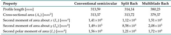
The second moments of area can be expressed through Eq. 1, where the averaged second moment of area in the xy plane is constant in any azimuth position 23, 24. Likewise, Iz can be used as the characteristic dimension of the second moment of area (Fig. 2).


Figure 2: Reference system used to determine the second moments of área
Numerical análisis
This study was carried out through the multiphysical analysis of a two-way fluid-structure interaction, which allows for feedback between the results of each of the physics involved, linking tools of computational fluid dynamics (CFD) with those of computational solid mechanics (CSM) 29, 34
The three geometries were studied in a steady state, employing the same CFD and CSM algorithms, parameters, and models via the ANSYS Fluent and Mechanical solvers, which solve the physics of each phenomenon through the finite volume and the finite element methods, respectively 35, 41.
The ANSYS Workbench automatically exchanges data between simulation solvers. Its mesh mapping technology ensures that data are transferred more accurately from CFD analysis to CSM and vice versa (Fig. 3)

Figure 3: Two-way fluid-structure interaction for the study case
This coupling considers the pressure field of the fluid dynamic analysis and the consequences of this load in the structural analysis. A limit of five calculation cycles or iterations in the two-way coupling was established.
A turbulence model k − ω SST was proposed due to its good performance in predicting free and adverse pressure gradient flows 42, 44. The convergence criterion for the solution residuals was fixed in the order of 10−3 .
The domain of analysis comprises two bodies: a fluid body and a solid body. The fluid body is made up of two parts: an orthohedral region that simulates the far fluid field, and a cylindrical one for the near fluid field, which contains the geometry of the rotor.
An air inlet was established at a velocity of v = 4 m/s (wind class 1) 45, corresponding to a flow regime with a Reynolds number of 6 × 10⁴ . Likewise, the outlet was fixed at atmospheric conditions, and the side field was simulated under symmetry conditions, since it is there that low-scale gradients occur 42, 46
The rotor walls rotate at a fixed angular velocity ω = 20 rad/s, corresponding to a T SR = 0, 5, in whose proximity the greatest torque load occurs (Fig. 4) 13
The speed ratio at the tip of the blade (T SR) gives a proportion of the angular velocity of the rotor in dimensionless terms, according to Eq. 2


Figure 4: Experimentally obtained CT results by the three tested rotors (E) and their comparison with the numerical results determined from the three-dimensional simulations (N) Source: 13
The torque coefficient (CT ) is estimated as the ratio between the torque generated by the rotor on its shaft (T) and the torque that is possible to generate under the given conditions 47,48. This is expressed by Eq. 3, where ρ is the density of the air and A = DH is the frontal area of the rotor.

The dimensions of the computational domain were set as follows: 10 m wide, 1 m high, and 10 m long, seeking to reduce the blockage effect caused by the rotor in the flow section (Fig. 5) 49, 50)

Figure 5: Three-dimensional analysis domain and its boundary conditions
In order to obtain an efficient number of partitions into which the analyzed domain had to be divided, it was necessary to carry out an independence analysis for spatial discretization, seeking to obtain convergence in the result. The rotor with the conventional semicircular profile was used as a test model during the independence analysis.
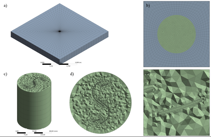
Since the model was made up of two bodies, an independence analysis was carried out for each of them. For the fluid body, five discretizations (known as meshing) were built with the same structure, but with an increased number of partitions in each edge according to the refinement of each mesh. The region that simulated the far field of the fluid had a structured mesh with only hexahedral elements (Figs. 6a and 6b), while the region that simulated the fluid field near the rotor had an unstructured mesh with only tetrahedral elements in order to gain greater adaptability to the geometry (Figs. 6c and 6d). The meshing adjacent to the rotor walls was refined and had a structure of perpendicular layer (inflation) that allowed for a better prediction of the boundary layer (Fig. 6e).

Figure 6: General structure of the meshing for the CFD analysis of the multiblade Bach rotor: (a) region far field of the fluid, (b) detail of the transition from the far field to the near field of the fluid, (c) cutaway view of region near field of the fluid, (d) profile geometry detail, and (e) detail of the profile walls
In the same way, for the solid body that simulated the rotor, five meshings were built, which were defined by predominant hexahedral elements forming structured faces on the walls of the blades (Fig. 7).

Figure 7: General structure of the meshing for the CSM analysis of the multiblade Bach rotor: (a) isometric view of the rotor model and (b) detail of the model walls
When solving each case with the different meshings, the maximum equivalent stress value was obtained, whose variation was observed to become smaller as the meshing became finer (Tables II and III). For fluid and solid body analysis, the asymptotic convergence indicators, according to the Richardson extrapolation, were 1,0042 and 1,0289, respectively, whose closeness to the unit indicates the existence of a convergence value 51.
For the meshing of the fluid body, the value of y + was also analyzed, which is recommended to be lower than the unit when using the turbulence model k − ω SST, thus ensuring appropriate predictions in the flow near the walls 42. In this way, the third meshing was selected for both the fluid and the solid bodies.
Table II: Mesh independence test results for the fluid body

Table III: Mesh independence test results for the solid body

The supports and the loads of the model were considered as shown in Fig. 8. A fixed support was located in the lower hub of the rotor, simulating a full load exerted by the generator. Similarly, a cylindrical support was placed on the upper hub, simulating the restriction in the bearing. Additionally, the aerodynamic loads imported from the fluid dynamic analysis were applied to the rotor surface.
In this analysis, the loads on the rotor body (weight and centripetal force) were not taken into account, since they are not linearly scalable, given their dependence on the mass, so the result could not be generalized (mass ∝ scale3 ).
Polyethylene was defined as the construction material, as it is a commonly used medium-strength polymer. Table IV shows its main structural properties.
Table IV: Established properties for polyethylene as a construction material
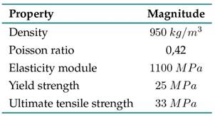

Figure 8: Established supports and loads for the multiblade Bach rotor model
Results
Results análisis
After solving the fluid physics, each rotor’s states of pressure and flow velocity were obtained. Fig. 9 shows the state of static pressure exerted by the fluid on the walls of the multiblade Bach rotor model by means of a contour graph. In the same figure, the fluid path lines and the corresponding velocity magnitude are shown for a flow plane. Areas of laminar flow, stagnation, recirculation, and fluid acceleration can be identified.

Figure 9: Results of the fluid dynamics on the multiblade Bach rotor for a wind of 4 m/s and a T SR of 0,5
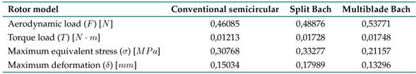
After transferring the result of the fluid dynamics analysis to the structural one, the stress and deformation states for each rotor were obtained, whose maximum values are summarized in Table V. Fig. 10 shows, represented by contours, an example of the multiblade Bach rotor’s state of stress and deformation.
Figure 10. State of equivalent stress (left) and total deformation (right) of the multiblade Bach rotor for a wind of 4 m/s and a T SR of 0,5
Table V: Structural analysis results
Discussion
As seen in Table V, the aerodynamic loads exerted on the rotor models vary as a result of the different profile shapes. These differences in loading conditions hinder a direct comparison of the structural results.
Because the generated torque is a consequence of the aerodynamic load, it is necessary to obtain a static equivalence that explains its origin, as each profile has different capabilities when it comes to converting this aerodynamic load into useful torque. Likewise, these differences in torque induce variations in the stress and strain state of the rotor.

Figure 10: State of equivalent stress (left) and total deformation (right) of the multiblade Bach rotor for a wind of 4 m/s and a T SR of 0,5
Eq. (4) describes the equivalent percentage of the aerodynamic load, which, when applied to the blade tip, is responsible for the generated torque, with eload being the load effectiveness.

In the same way, when comparing the second polar moment of area with the maximum moment that can be obtained with the same area, the effectiveness in the distribution of the profile area with regard to the rigidity of the structure can be explained. Eq. (5) allows obtaining the maximum second polar moment of area given the cross-sectional area and the diameter. Likewise, Eq. (6) shows this relationship, where earea is the area effectiveness.


By determining the ratio for each rotor model, the values plotted in Fig. 11 are obtained. It can be seen that the conventional semicircular profile has the least load effectiveness, i.e., it generates great aerodynamic resistance while delivering low torque. In contrast, the split Bach profile offers the greatest load effectiveness, allowing a higher torque to be achieved with less resistance. Although the load effectiveness of the multiblade Bach profile is between that of the two previous profiles, its value is greater than the average of the two. This shows that the aerodynamic load exerted on the multiblade Bach rotor is the highest, as a consequence of a greater power transmisión.

Figure 11: Load (left), area (center), and structural (right) effectiveness in profile geometries. Black lines represent the average effectiveness for the conventional semicircular and split Bach profiles.
On the other hand, the greatest area effectiveness is reported by the conventional semicircular profile, which shows a greater concentration of area in the outermost region of the geometry of the profile. In contrast, the least area effectiveness is observed in the split Bach profile, indicating that the area is more concentrated towards the center of the geometry. Although the area effectiveness of the multiblade Bach profile is between that of the two previous profiles, its value is greater than the average of the two.
Both indicators were multiplied to obtain a structural effectiveness value which showed that the changes made to the geometries, starting from the conventional semicircular profile, had positive impacts on structural stability. An increasing trend in the evolution of the rotor can be seen by means of this indicator.
Considering that the stresses and deformations (σ, δ) are directly proportional to the loads (F, T) 23, 24, it is possible to adjust the results of the conventional semicircular and split Bach rotors to the loading conditions of the multiblade Bach. To this effect, the compound proportionality method described in Eq. (7) is implemented.

where the subscripts adj, i, and j refer to the adjusted value, rotor i, and rotor j (multiblade Bach rotor in this case), respectively. Thus, the values reported in Table V were adjusted under the same load conditions of the multiblade Bach profile and are presented in Fig. 12
The results in Fig. 12 reveal a consistent trend with the structural effectiveness results (Fig. 11), with the values of the adjusted maximum equivalent stress and deformation being significantly lower for the multiblade geometry, which indicates that the multiblade Bach profile offers greater strength and stiffness.
The adjusted maximum equivalent stresses were reduced by 59,10 and 42,87 %, and the deformations by 47,40 and 33,59 % with respect to the conventional semicircular and split Bach profiles, respectively.

Figure 12: Adjusted maximum equivalent stress and deformation for each rotor
This additional structural stability is provided by the greater moment of area provided by the secondary element of the multiblade profile, where the Iz of the multiblade Bach profile is 42,47 % greater than that of the split Bach.
The mass moment of inertia (IM) is directly proportional to the second polar moment of area, with the constant of proportionality being the product between the density of the construction material (ρM) and the height of the blade, as described in Eq. (8).

Therefore, as the second polar moment of area increases, the mass moment of inertia also increases. This means a greater difficulty for the rotor to start its movement. However, in the case of the multiblade profile, this is compensated by the higher static torque that is generated when the rotor starts up (Fig. 4) 13. Additionally, a greater inertia reduces the fluctuation of the torque transmitted, working as a flywheel.
Conclusions
This study compared the structural behavior under aerodynamic loads of rotors with conventional semicircular, split Bach, and Bach multiblade profiles. The models were studied via a two-way fluid-structural interaction analysis and in a steady state.
The results revealed that the multielement rotor had greater strength and stiffness, provided by the increase in the second polar moment of area implied by the secondary element in the profile. The maximum equivalent stresses were reduced by 59,10 and 42,87 %, and the deformations by 47,40 and 33,59 % with regard to the conventional semicircular and split Bach profiles, respectively.
The implementation of the secondary element allows for a greater aerodynamic and structural performance, preserving, to a large extent, the construction and operation simplicity that characterizes Savonius-type rotors, requiring an addition of only 21 % of the material involved for manufacturing the main elements.
Acknowledgements
Acknowledgments
The authors gratefully acknowledge the financial support provided by the Colombia Scientific Program within the framework of call Ecosistema Científico [contract number FP44842-218-2018]
References
License
Copyright (c) 2023 Luis Antonio Gallo Jaramillo, Edwin Lenin Chica Arrieta, Elkin Gregorio Flórez Serrano

This work is licensed under a Creative Commons Attribution-NonCommercial-ShareAlike 4.0 International License.
![]()
From the edition of the V23N3 of year 2018 forward, the Creative Commons License "Attribution-Non-Commercial - No Derivative Works " is changed to the following:
Attribution - Non-Commercial - Share the same: this license allows others to distribute, remix, retouch, and create from your work in a non-commercial way, as long as they give you credit and license their new creations under the same conditions.

2.jpg)