DOI:
https://doi.org/10.14483/23448393.16562Published:
2021-05-30Issue:
Vol. 26 No. 2 (2021): May - AugustSection:
Electrical and Electronic EngineeringVision-based Software Tool System for Position Estimation Using a Smartphone
Sistema de herramientas software basado en visión para la estimación de posición usando un teléfono inteligente
Keywords:
Smartphone, Position estimation, Computer vision (en).Keywords:
Teléfono inteligente, estimación de posición, visión por computador (es).Downloads
References
S. Bianco, G. Ciocca, and D. Marelli, “Evaluating the Performance of Structure from Motion Pipelines,” J. Imaging, vol. 4, no. 8, p. 98, Aug. 2018. https://doi.org/10.3390/jimaging4080098 DOI: https://doi.org/10.3390/jimaging4080098
M. O. A. Aqel, M. H. Marhaban, M. I. Saripan, and N. B. Ismail, “Review of visual odometry: types, approaches, challenges, and applications,” Springerplus, vol. 5, no. 1, p. 1897, Dec. 2016. https://doi.org/10.1186/s40064-016-3573-7 DOI: https://doi.org/10.1186/s40064-016-3573-7
H. Durrant-whyte and T. Bailey, “Simultaneous Localisation and Mapping ( SLAM ): Part I The Essential Algorithms,” IEEE Robot. Autom. Mag., vol. 13, no. 2, pp. 99–110, 2006. https://doi.org/10.1109/MRA.2006.1638022 DOI: https://doi.org/10.1109/MRA.2006.1638022
A. Astudillo, B. Bacca, and E. Rosero, “Optimal and robust controllers design for a smartphone-based quadrotor,” in 2017 IEEE 3rd Colombian Conference on Automatic Control (CCAC), 2017, pp. 1–6. https://doi.org/10.1109/CCAC.2017.8276392 DOI: https://doi.org/10.1109/CCAC.2017.8276392
G. Klein and D. Murray, “Parallel Tracking and Mapping on a camera phone,” in 2009 8th IEEE International Symposium on Mixed and Augmented Reality, 2009, pp. 83–86. https://doi.org/10.1109/ISMAR.2009.5336495 DOI: https://doi.org/10.1109/ISMAR.2009.5336495
J. Ventura, C. Arth, G. Reitmayr, and D. Schmalstieg, “Global Localization from Monocular SLAM on a Mobile Phone,” IEEE Trans. Vis. Comput. Graph., vol. 20, no. 4, pp. 531–539, Apr. 2014. https://doi.org/10.1109/TVCG.2014.27 DOI: https://doi.org/10.1109/TVCG.2014.27
M. Cao, L. Zheng, W. Jia, and X. Liu, “Fast monocular visual odometry for augmented reality on smartphones,” IEEE Consum. Electron. Mag., pp. 1–1, 2020. https://doi.org/10.1109/MCE.2020.2993086 DOI: https://doi.org/10.1109/MCE.2020.2993086
L. Jin, H. Zhang, and C. Ye, “Camera Intrinsic Parameters Estimation by Visual–Inertial Odometry for a Mobile PhoneWith Application to Assisted Navigation,” IEEE/ASME Trans. Mechatronics, vol. 25, no. 4, pp. 1803–1811, Aug. 2020. https://doi.org/10.1109/TMECH.2020.2997606 DOI: https://doi.org/10.1109/TMECH.2020.2997606
S. Tomažiˇc and I. Škrjanc, “Monocular Visual Odometry on a Smartphone,” IFAC-PapersOnLine, vol. 48, no. 10, pp. 227–232, Jan. 2015. https://doi.org/10.1016/j.ifacol.2015.08.136 DOI: https://doi.org/10.1016/j.ifacol.2015.08.136
F. G and C. JM, “Indoor Localization using Computer Vision and Visual-Inertial Odometry.,” Comput. Help. People with Spec. Needs ... Int. Conf. ICCHP ... proceedings. Int. Conf. Comput. Help. People with Spec. Needs, vol. 10897, pp. 86–93, Jun. 2018. https://doi.org/10.1007/978-3-319-94274-2_13 DOI: https://doi.org/10.1007/978-3-319-94274-2_13
D. Agudelo España, D. Gil López, and S. Silva López, “Estimación de la localización de un vehículo usando un sistema de visión por computador,” Universidad Tecnológica de Pereira, Grupo de Investigación SIRIUS, 2013. http://repositorio.utp.edu.co/dspace/bitstream/handle/11059/4132/00637A282E_Anexo.pdf?sequence=2&isAllowed=y
T. Schops, J. Engel, and D. Cremers, “Semi-dense visual odometry for AR on a smartphone,” in 2014 IEEE International Symposium on Mixed and Augmented Reality (ISMAR), 2014, pp. 145–150. https://doi.org/10.1109/ISMAR.2014.6948420 DOI: https://doi.org/10.1109/ISMAR.2014.6948420
M. Li, R. Chen, X. Liao, B. Guo, W. Zhang, and G. Guo, “A Precise Indoor Visual Positioning Approach Using a Built Image Feature Database and Single User Image from Smartphone Cameras,” Remote Sens., vol. 12, no. 5, p. 869, Mar. 2020. https://doi.org/10.3390/rs12050869 DOI: https://doi.org/10.3390/rs12050869
Y.-H. Jin, K.-W. Ko, and W.-H. Lee, “An Indoor Location-Based Positioning System Using Stereo Vision with the Drone Camera,” Mob. Inf. Syst., vol. 2018, pp. 1–13, Oct. 2018. https://doi.org/10.1155/2018/5160543 DOI: https://doi.org/10.1155/2018/5160543
Z. Shang and Z. Shen, “Vision-model-based Real-time Localization of Unmanned Aerial Vehicle for Autonomous Structure Inspection under GPS-denied Environment,” in The 2019 ASCE International Conference on Computing in Civil Engineering, 2019, pp. 1–8. https://doi.org/10.1061/9780784482445.037 DOI: https://doi.org/10.1061/9780784482445.037
M. Werner, M. Kessel, and C. Marouane, “Indoor positioning using smartphone camera,” in 2011 International Conference on Indoor Positioning and Indoor Navigation, 2011, pp. 1–6. https://doi.org/10.1109/IPIN.2011.6071954 DOI: https://doi.org/10.1109/IPIN.2011.6071954
F. Jabborov and J. Cho, “Image-Based Camera Localization Algorithm for Smartphone Cameras Based on Reference Objects,” Wirel. Pers. Commun., vol. 114, no. 3, pp. 2511–2527, Oct. 2020. https://doi.org/10.1007/s11277-020-07487-9 DOI: https://doi.org/10.1007/s11277-020-07487-9
R. Mur-Artal, J. M. M. Montiel, and J. D. Tardos, “ORB-SLAM: A Versatile and Accurate Monocular SLAM System,” IEEE Trans. Robot., vol. 31, no. 5, pp. 1147–1163, Oct. 2015. https://doi.org/10.1109/TRO.2015.2463671 DOI: https://doi.org/10.1109/TRO.2015.2463671
E. Rublee, V. Rabaud, K. Konolige, and G. Bradski, “ORB: An efficient alternative to SIFT or SURF,” 2011 Int. Conf. Comput. Vis., pp. 2564–2571, 2011. https://doi.org/10.1109/ICCV.2011.6126544 DOI: https://doi.org/10.1109/ICCV.2011.6126544
P. Kruchten, The Rational Unified Process: An Introduction, 3rd ed. Addison-Wesley Professional, 2003
J.-Y. Bouguet, “Camera Calibration Toolbox for Matlab,” California Institute of Technology, 2013. [Online]. Available: http://www.vision.caltech.edu/bouguetj/calib_doc/
M. Karaim, M. Elsheikh, and A. Noureldin, “GNSS Error Sources,” in Multifunctional Operation and Application of GPS, InTech, 2018. https://doi.org/10.5772/intechopen.75493 DOI: https://doi.org/10.5772/intechopen.75493
How to Cite
APA
ACM
ACS
ABNT
Chicago
Harvard
IEEE
MLA
Turabian
Vancouver
Download Citation
Recibido: 24 de junio de 2020; Revisión recibida: 7 de mayo de 2021; Aceptado: 11 de mayo de 2021
Abstract
Context:
Current smartphone models have a very interesting set of sensors such as cameras, IMUs, GPS, and environmental variables. This combination of sensors motivates the use of smartphones in scientific and service applications. One of these applications is precision agriculture, specifically drone position estimation using computer vision in GPS-denied environments for remote crop measurements.
Method:
This work presents the development of EVP, a vision-based position estimation system using a modern smartphone and computer vision methods. EVP consists of two software applications: an Android app (mobile station) running on a smartphone capable of controlling the drone’s flight, acquiring images, and transmitting them through a wireless network; and another application (base station) running on a Linux-based computer capable of receiving the images, processing them and running the position estimation algorithms using the acquired images. In this work, the mobile station is placed in a quadcopter. Using EVP, users can configure the mobile and base station software, execute the vision-based position estimation method, observe position graph results on the base station, and store sensor data in a database.
Results:
EVP was tested in three field tests: an indoor environment, an open field flight, and a field test over the Engineering Department’s square at Universidad del Valle. The root mean square errors obtained in XY were 0,166 m, 2,8 m, and 1,4 m, respectively, and they were compared against the GPS-RTK measurements.
Conclusions:
As a result, a vision-based position estimation system called EVP was developed and tested in realworld experiments. This system can be used in GPS-denied environments to perform tasks such as 3D mapping, pick-up and delivery of goods, object tracking, among others.
Acknowledgements:
This work was partially funded by the research project “Autonomous Aerial System to Map the Nitrogen Contents in Crops using Micro-Spectral Sensors”, contract CI2961 of Universidad del Valle.
Keywords:
Smartphone, position estimation, computer vision..Resumen
Contexto:
Los actuales modelos de teléfonos inteligentes tienen un conjunto muy interesante de sensores como cámaras, IMUs, GPS y variables ambientales. Esta combinación de sensores motiva el uso de los teléfonos inteligentes en aplicaciones científicas y de servicio. Una de estas aplicaciones es la agricultura de precisión, específicamente la estimación de posición de un dron usando visión por computador para realizar mediciones remotas en cultivos.
Método:
Este trabajo presenta el desarrollo de EVP, un sistema de estimación de posición basado en visión usando un teléfono inteligente moderno y métodos de visión por computador. EVP consiste en dos aplicaciones software, una app de Android (estación móvil) ejecutándose en un teléfono inteligente capaz de controlar el vuelo de un dron, capturar imágenes, y transmitirlas a través de una red inalámbrica; y otra aplicación (estación base) ejecutándose en un PC Linux capaz de recibir imágenes, procesarlas y ejecutar los algoritmos de estimación de posición usando las imágenes adquiridas. En este trabajo, la estación móvil está ubicada en un cuadracóptero. Usando EVP, los usuarios pueden configurar el software de la estación móvil y base, ejecutar el método de estimación de posición basado en visión, observar resultados gráficos de la posición en la estación base y almacenar los datos adquiridos en una base de datos.
Resultados:
EVP fue probada en tres pruebas de campo: en ambientes de interiores, un vuelo en campo abierto, y sobre la plazoleta de la Facultad de Ingeniería de la Universidad del Valle. Los errores cuadráticos medios en XY fueron 0,166 m, 2,8 m y 1,4 m respectivamente y comparados con las medidas de GPS-RTK.
Conclusiones:
Como resultado, un sistema de estimación de posición basado en visión llamado EVP fue desarrollado y probado en experimentos reales. Este sistema puede ser usado en ambientes sin señal de GPS para realizar tareas como mapeo 3D, recogida y entrega de materiales, seguimiento de objetivos, entre otros.
Agradecimientos:
Este trabajo fue parcialmente financiado por el proyecto de investigación “Sistema Aéreo Autónomo para Mapear el Contenido de Nitrógeno en Cultivos usando Sensores Microespectrales”, contrato CI2961 de la Universidad del Valle.
Palabras clave:
Teléfono inteligente, estimación de posición, visión por computador..Introduction
Nowadays, smartphones have a high CPU performance, many communication procotols (Wi-Fi, Bluetooth, NFC, etc.), and a set of specialized sensors (GPS, inertial measurement units, cameras, pressure, light, etc.). Using these sensors individually or together generates novel development and research options for applications involving position estimation, where GPS-based methods are most popular. However, update rate, precision, and signal availability are serious concerns regarding this method. On the other hand, fine camera motions can be tracked using popular computer vision techniques such as structure-from-motion [1], visual odometry [2], bundle-adjustment [1], and simultaneous and localization and mapping [3]. Nevertheless, all these methods are computationally expensive, and their implementation into a mobile phone is not straight-forward, which is why this work describes the development of EVP, a visual-based software system to estimate the position of a smartphone without relying on any external infrastructure or prior knowledge of the environment.
Using handheld devices for position estimation opens several research and application horizons. For instance, this work was developed as a part of a research project in the context of precision agriculture, where UAV (quadcopters) platforms are used to sense nitrogen signatures in crops using micro-spectral devices. To do so, UAVs must follow a pre-computed path to perform the corresponding measurements. This is the global task in the Autonomous Aerial System to Map the Nitrogen Contents in Crops using Micro- Spectral Sensors research project of Universidad del Valle, where this work will play the role of following the crop tracks. Additionally, other applications are building collaborative mosaics using several drones of wide farmlands or carrying out inspection tasks on civil structures using low-cost drones. Therefore, the visual-based software system for position estimation described in this work (Fig. 1) was developed in two parts: first, the base station, which allows users to configure the motion estimation algorithms, acquiring remote images from a drone, estimating the smartphone position, and visualizing the camera trajectory in a user-friendly GUI; and second, the mobile application, which transmits telemetry and image data to the base station. It is worth noting that the quadcopter flight controller in this work is implemented into the smartphone [4] using its built-in inertial sensors and its computational and communication capabilities.
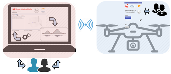
Figure 1: EVP system overview
This work is structured as follows: section 2 describes the related works; section 3 contains the background concepts of monocular position estimation; section 4 shows the design and implementation of EVP; section 5 presents the tests performed and their results; and section 6 is dedicated to our conclusions.
Related works
Table I summarizes the most relevant works related to this paper, which emphasize on position estimation using mobile devices and computer vision methods. These works were compared considering properties such as the computational platform used, the position computation method, the type of tests performed, camera resolution and orientation, the DOF computed by the algorithm, the speed of processing in FPS, and whether the algorithm runs on-line or off-line.
Table I: Related works
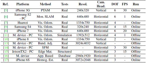
In Table I, the related works can be divided by the position estimation method, used in four categories as follows: SLAM (Simultaneous Localization and Mapping) based solutions, visual odometry methods, structure from motion approaches, and custom methods. SLAM-based solutions work using images with reduced resolution, due the computational cost of the SLAM pipeline. For instance, the best results reported correspond to [5], where a position error of up to 2,21 m in a field of 600 m2 was achieved. In this case, a PTAM (Parallel Tracking Mapping) method was used to estimate the 6DOF of the smartphone. In [6], the authors propose position estimation methods based on monocular and EKF SLAM, respectively. However, as shown in Table I, the processing speeds achieved were not high enough to be used in dynamic environments.
To estimate the position of a mobile vehicle in space while reducing the computational cost, other methods lighter than SLAM-based approaches could be explored. That is the case of the works in Table I that use visual odometry. In [7], the authors propose a position estimation system based on visual odometry methods using a Huawei smartphone, which is used for augmented reality applications. In [8], a visual odometry system is proposed for applications involving assisted navigation for blind people, where a graph model of the environment is computed. Some visual odometry methods implemented in the works shown in Table I perform well, considering some constraints such as putting artificial landmarks in the environment [9], [10], or working along short distances [11]. In [9], [11], and [10], these constraints had to be kept in mind, given that loop closure computations were not considered. However, in [12], the authors are continuously building a semi-dense map and matching the current image with it to estimate the smartphone’s position in real time. This position estimation method is used for indoor augmented reality applications.
Another option for position estimation of a mobile device with constrained computation resources is to divide the estimation process in two parts: one part corresponds to heavy calculations, and another one to mobile data acquisition. This strategy is observed in various works in Table I, especially those corresponding to structure from motion and custom methods. Structure from motion-based methods involve heavy computation procedures, but they yield very precise results. For this reason, in [13] and [14], two main steps are considered: first, a mapping stage where a previous map is computed; and second, a localization stage where the mobile device (a smartphone in [13] and a drone in [14] remotely receives the position estimation. In both cases, bundle adjustment and structure from motion methods are used to estimate the position of the mobile device using non-linear minimization approaches of the re-projection error in a set of continuous images.
Custom methods to estimate mobile device position in space are also used. In [15] , [16] , and [17] , the authors propose two appearance-based methods to estimate relative position. In [15] , the authors use an edge-based matcher in structured environments to compute the relative position of a small drone. In [16] , they use a pre-loaded image database, SURF features, and the smartphone’s camera data to estimate the user position in 1D indoors environments such as hallways. In these cases, most of the hard work is done remotely, and it assumes that the environment was previously mapped. In [17] , an optimal homography computation method is proposed; in this approach, markers are used to validate the planar constraint when computing the homography matrix.
Table I describes important properties when it comes to developing a position estimation system that uses a mobile device. EVP was developed considering the following properties: first, it is divided in two parts, one focused on the position calculation (base station, where CPU-demanding algorithms are executed) and another one in data acquisition (smartphone). Second, although visual odometry methods could be used, SLAM-based methods constitute a more compact solution. For this reason, this study uses the ORB- SLAM approach [18] . Third, to constraint the communication bandwidth and the processing time, the captured images must have a reduced resolution. Fourth, horizontal camera orientation is preferred to increase the time in which image features can be tracked. Finally, online operation is desired.
Monocular vision-based position estimation
According to Fig. 1, the position estimation system proposed for this work includes one monocular camera, which is why, in this work, position estimation is done using monocular SLAM, specifically with the ORB-SLAM approach [18] . In this approach, the camera position is defined with respect to a reference coordinate frame W. At each time instant k, the camera position can be defined using the element
 , where T
k
defines a transformation of coordinates between W and the camera center of projection C. Then, any point in space p with respect to W can be projected into an X image point using Eq. (1):
, where T
k
defines a transformation of coordinates between W and the camera center of projection C. Then, any point in space p with respect to W can be projected into an X image point using Eq. (1):

Where K is the intrinsic calibration matrix, T hk is the camera position in homogeneous coordinates, P is the 3D space point in homogenous coordinates, and X is the image point in homogenous coordinates. Then, all interest points automatically detected in ORB-SLAM use Eq. (1) to get their representation in image space. These interest points are binary features called ORB [19]. In comparison with their counterparts, such as SIFT or SURF, ORB image descriptors are faster to detect and match. By using these image descriptors, ORB-SLAM implements a bundle adjustment approach in conjunction with a key frame selection method to estimate the 3D location in space of the ORB features.
While using these 3D features at each bundle of images, three threads are running: tracking, local mapping, and loop closing. The aim of the tracking thread is to estimate the camera position at every frame and decide when a key frame is to be inserted to boost the bundle adjustment algorithm. Then, using the key frames detected so far, local mapping is built using local bundle adjustment; additionally, this algorithm is used to remove low quality features and redundant key frames. In the context of SLAM methods, it is important to solve the loop closure problem. In ORB-SLAM, this is done by means of similarity measurements each time a key frame is detected. If a loop closure is detected, a position graph optimization process is performed. All these tasks are detailed in the following subsections to understand how the position of the drone is estimated in this work.
Initialization
At the very beginning, image features must be initialized properly, even though the scene may have planar or non-planar structures. First, ORB features are extracted from current frame F
c
and reference frame F
r
. Then, correspondences are found in frames
 . Second, homography and the fundamental matrix are robustly computed using Eq. (2):

The homography and fundamental matrix models are scored [18], and only one is selected to estimate the initial relative motion until the second key frame is selected. Along this trajectory, local bundle adjustment is performed to optimize camera position.
Tracking
The tracking thread in ORB-SLAM uses the ORB descriptors computed from FAST corners in the current image frame F r [18] . Then, a constant velocity model is implemented to predict the camera position and use it to search map points already stored in other neighboring key frames. This search is performed by projecting a local map of key points into the current frame F C . The camera position is optimized with all the map points found that satisfy a specific set of conditions. First, the re-projection error of map key points must be minimized using Eqs. (3) and (4):
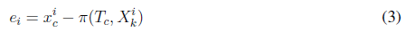
Where e
i
is the i-th re-projection error of the i-th key point in the local map,
 is the i-th key point in the image, π is the re-projection function, which depends on the current camera position T
c
and the 3D world map point
is the i-th key point in the image, π is the re-projection function, which depends on the current camera position T
c
and the 3D world map point
 , C is the function to minimize which depends on the Huber robust cost function δ, and Ω is the uncertainty with respect to the scale. Second, all key points which viewing direction, compared to the map mean viewing direction that are less than cos(60°) are kept. Also, all key points which are outside the map scale invariance region must be discarded. Once the camera position is tracked, the insertion of key frames depends on conditions such as the number of frames from the last global re-localization, the number of frames from the last key frame insertion, the minimum number of map points tracked, and the percentage of map points tracked since F
r
.
, C is the function to minimize which depends on the Huber robust cost function δ, and Ω is the uncertainty with respect to the scale. Second, all key points which viewing direction, compared to the map mean viewing direction that are less than cos(60°) are kept. Also, all key points which are outside the map scale invariance region must be discarded. Once the camera position is tracked, the insertion of key frames depends on conditions such as the number of frames from the last global re-localization, the number of frames from the last key frame insertion, the minimum number of map points tracked, and the percentage of map points tracked since F
r
.
Local mapping
The local mapping thread tracks the points as described in Section 3.2 and checks if they are observed for at least three key frames [18] . Then, if those points have no previous matches with other map points, they are added to the current local map. This means that these new points are linked with the corresponding key frame in the local graph representation. Afterwards, local bundle adjustment (Eqs. (3) and (4)) is performed using the current frame F c and all neighbor key frames that are related to F c through the shared ORB features. This is done to refine the camera positions in the graph map representation. Finally, in this thread, key frame removing is performed if 90% of the ORB features are observed in at least other three key frames.
Loop closure
In parallel, the loop closing thread uses the current processed key frame F c and tries to detect loop closure events. To do so, a robust and dynamic bag-of-words approach is performed [18] each time a key frame is added to the graph map. By using this bag of words, all current ORB features belonging to the current key frame are used to find correspondences with other key frames (at least 30 neighbors). A loop closure candidate is accepted if it is possible to track it in at least 3 key frames. Then, using all the key frame candidates Fl and their correspondences with the current frame FC, a transformation similarity is computed to know the geometric error accumulated in the loop. This relative similarity optimization is described in Eqs. (5) and (6).
Where e
1
and e
2
define the re-projection errors between key frame 1 and 2;
 and
and
 are the corresponding ORB features; π
1
and π
2
are the projection functions at each key frame; S
1,2
is the relative transformation between key frames 1 and 2; X
1,i
and X
2,j
are the corresponding 3D map points;
are the corresponding ORB features; π
1
and π
2
are the projection functions at each key frame; S
1,2
is the relative transformation between key frames 1 and 2; X
1,i
and X
2,j
are the corresponding 3D map points;
 and
and
 are the covariances matrices associated to scale at each key frame; and C is the cost function to minimize. Then, the selected loop closure candidate will be the one that better explains the geometric constraints of all key frames and common correspondences with F
C
in the loop.
are the covariances matrices associated to scale at each key frame; and C is the cost function to minimize. Then, the selected loop closure candidate will be the one that better explains the geometric constraints of all key frames and common correspondences with F
C
in the loop.
Development of EVP
As depicted in Fig. 1, EVP was developed in two main parts, namely the base station and the mobile device. The base station allows users to configure, compute, and monitor the position estimation of a drone. This process is a CPU-demanding task that is performed off-board the drone. The flight controller of the drone (mobile station) is based on an Android smartphone, which is also in charge of acquiring and transmitting images to the base station. Therefore, two software developments are present in this work, which are described in detail in the following sections, considering the RUP [20] methodology for software engineering. This software development methodology includes various design and test documents, but, to keep this document short, only the functional and non-functional requirements, concept diagram, and class diagrams are described in this work.
Design of EVP
Considering the analysis of the related works presented in section 2, the functional and nonfunctional requirements for the EVP software tool in the base station are detailed below:
-
Functional requirements: Users are able to configure the position estimation algorithm using a friendly GUI; they are able to set all the flight mission parameters using a friendly GUI; and they are able to start, stop, and resume a flight mission using the GUI. EVP must allow connecting with the drone, using wireless communication to receive the acquired images; it uses the images to estimate the drone’s position in space. Users are able to visualize the estimated position graphically, and EVP must send the estimated position to the drone.
-
Non-functional requirements: the development environment is based on Java 8, update 121. EVP uses the jmatplot API to show the estimated position, and it uses OpenCV version 3.4. EVP runs on Ubuntu Linux 16.04.5. The IDE used to develop EVP is NetBeans 8.0.2.
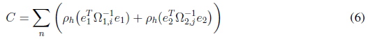
These functional requirements were mapped into the concept diagram shown in Fig. 2a. In this Figure, it can be observed that users in the base station can manage, configure, monitor, and operate the mission using the EVP GUI, which runs on the base station and is also in charge of communicating with the drone to send the configuration parameters and receive the images acquired by the smartphone. These images are used to compute the drone position off-board. Afterwards, this position is used in the base station to plot the graphs and then send them back to the drone.
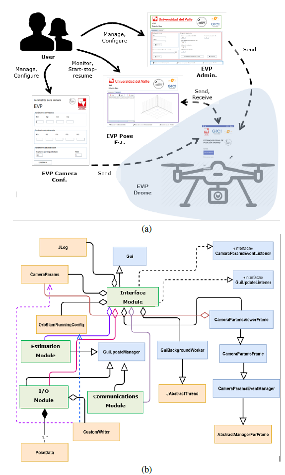
Figure 2: a) Conceptual diagram of the EVP base station software tool; b) EVP station base class diagram
Considering the functional requirements described above and the conceptual diagram depicted in Fig. 2a, the EVP base station software tool was implemented using the class diagram shown in Fig. 2b. In this diagram, the EVP station base software was divided into three packages: GUI event handlers (blue boxes), data processing (orange boxes), and GUI containers (green boxes). GUI event handlers implement all the actions to perform when a graphical component issues an event; all these graphical components are implemented in the GUI containers and they allow parameterizing the EVP position estimation approach used, as well as configuring the EVP software tool. Also, the data processing packages include the ORB- SLAM main thread, the plotting tools, and different support classes to communicate results with other packages.
All the communications sent and received by the EVP GUI in the base station are issued by the smartphone in the drone. An Android application was also developed, and its functional and non-functional requirements are listed below:
-
Functional requirements: users can enable or disable the communication module. The EVP app is able to communicate using a wireless link to the base station; it app must acquire images using the smartphone camera; and it must be able to send the images acquired and receive the estimated position of the drone from the base station.
-
Non-functional requirements: Android studio version 2.0 is used to develop the EVP app. The development language is Java 7, update 121. To acquire and pre-process the images, OpenCV 3.0 is used. A flight controller based on Java running on the smartphone is used.
Fig. 3a shows the conceptual diagram of the EVP app’s mobile station. It runs on the smartphone, which is also in charge of flight control. The EVP app is remotely executed explicitly by users, and they must also enable or disable the communication module. Afterwards, if users enable the communication module, the data acquisition begins, sending images to the base station to estimate the drone’s position. This is due to the fact that the smartphone in the drone does not have enough CPU power to perform this calculation.
Figure 3: a) Conceptual diagram of the EVP mobile station software tool; b) EVP app class diagram
Considering the functional requirements of the EVP app and the conceptual diagram described above, the implementation of this EVP app was in accordance with the class diagram depicted in Figure 3b. In this Figure, it can be observed that three different packages were implemented: camera handling (yellow boxes), wireless link handler (green boxes), and miscellaneous tools (red boxes). The EVP app was implemented considering two modules and the main program. These two modules are the communication and data acquisition modules, which use the packages mentioned above to perform their tasks. It must be added that the EVP app’s main program is in charge of integrating all Android-based activities.
Description of the EVP software tool
As mentioned before, the EVP software tool has two main parts, and the interaction between the user, the EVP base station, and the EVP app assumes the following process:
-
The user starts the EVP base station software tool and the EVP mobile station on the smartphone.
-
The user configures the flight parameters using the EVP base station and sends them to the EVP mobile station.
-
The user starts the flight mission manually and then remotely enables the position estimation module in the EVP app.
-
The EVP mobile station starts receiving telemetry data and images from the quadcopter (mobile station). Then, the EVP base station computes the quadcopter’s position, visualizes the results, and sends the estimated position to the quadcopter. This data exchange takes place during the flight mission.
Fig. 4 shows the EVP base station’s GUI, which implements the functional requirements described in section 4.1. It is divided in three main parts: the first panel (green rectangle) shows the institutional logos; the second panel (red rectangle) allows users to configure the wireless link to the quadcopter, the folder where all data collected will be stored, and the basic ORB-SLAM parameters (the number of image features to detect, the number of decomposition levels for each image feature, the scale factor at each decomposition level for each image feature, the minimum initial number of features detected, and the minimum number of features detected in subsequent pair of frames); and a status panel (blue rectangle) where the wireless link and the communication and running status are shown.
An important aspect of the configuration panel in Figure 4 is defining the camera parameters. This is done by using the “Establish Camera Parameters” button. Then, a dialog shows up to modify the intrinsic cam- era parameters, the distortion coefficients, the FPS, and the color space used.
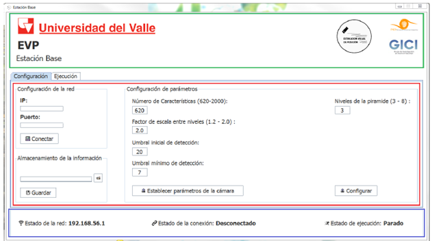
Figure 4: EVP base station GUI, configuration module
Afterwards, by clicking on the “Configure” button, all this information is stored in the base station and sent to the flight controller in the quadcopter’s smartphone. Afterwards, the position estimation algorithm of the quadcopter in the base station can be started.
At this point of the process, the user manually starts the flight mission and enables the position estimation module in the EVP mobile station. To this effect, Fig. 5a shows the EVP mobile station GUI, where the user selects the wireless network name and configures the communication port. The EVP base station and mobile station exchange data using a client/server communication. Once the communication is established, the EVP mobile station is activated, and it remotely enables the position estimation system.
Once the position estimation system is running in the base station, raw data is exchanged between the EVP base and mobile station using the frame structure depicted in Fig. 5b. This data frame is used to notify different events such as: connection/disconnection of the EVP mobile station, enable/disable commands for the position estimation system, and EVP status. At running state, the EVP mobile station continuously sends image data to the EVP base station at a fixed 640x380 resolution. Then, the EVP base station computes the quadcopter’s position and sends it back to the EVP mobile station using the position data field. This field contains the translation vector (t x ,t y ,t z ) and the unit quaternion (q w , q x , q y , q z ), which describes the current quadcopter’s position in space.
At the same time, in the EVP base station, users have all the corresponding functionalities, as shown in Fig. 6. In this Figure, users can start or stop the position estimation system, which agrees with the remote enable/disable functionality in the EVP mobile station. Also, users can visualize the current position of the quadcopter, and this position can be plotted in the EVP base station.
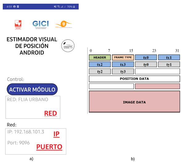
Figure 5: EVP app GUI; b) communication data frame structure
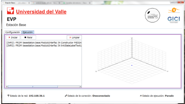
Figura 6: EVP base station GUI, position estimation module
Afterwards, the drone’s position is sent to the quadcopter.
Users can also observe a text log with all communication events during the flight mission. Finally, status information is shown at the bottom of the GUI, as depicted in Fig. 4.
Test and results
The experimentation platform is presented in Fig. 7. The hardware and software of this platform was designed and implemented in the context of [4]. As observed in Fig. 7, the smartphone (LG Nexus 5X, Android Nougat 7.1.1), which runs robust and optimal flight controllers, is placed below the quadcopter. The quadcopter used has a carbon fiber LJI 500-X4 frame. Moreover, the quadcopter has a radius of 0,3 m and a weight of 450 g, and it can lift a payload of 250 g. Also, this smartphone is running the EVP mobile app described in section 4. The smartphone’s camera is facing downwards to capture the images used to estimate the quadcopter’s position.
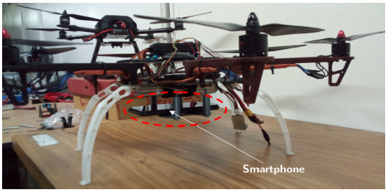
Figura 7: Quadcopter and the relative position of the smartphone (facing downwards)
The position estimation performed by the ORB-SLAM algorithm in the base station needs the camera calibration parameters. These parameters are listed as follows: the camera focus f x = 494, 081, 41, f y = 494, 161, 57; the main point is located at c x = 319; 852; 28 and c y = 173, 561, 74; and the distortion parameters are k 1 = 0, 040, 01, k 2 = -0, 090, 02, k3 = 0, 000, 00, p 1 = -0, 0140, 001, and p 2 = 0; 000; 00. These parameters where obtained using the Bouguet Matlab toolbox [21].
In this section, the results of three different tests are presented. First, the EVP software tool was tested using only the smartphone and describing a known circular indoor trajectory. The aim of this test was to check the position estimation functionalities in a controlled indoor environment. Second, an open field test was performed with the aim of validating the position estimation approach in low textured outdoors environments with EVP. Finally, a field test was conducted with the aim of checking the EVP position estimation in more textured outdoor environments. In all these tests, the EVP base station software tool was executed in a laptop Dell Vostro 3500, with an Intel Core i5 CPU, 6Gb of RAM, and running Ubuntu 16.04 LTS Xenial.
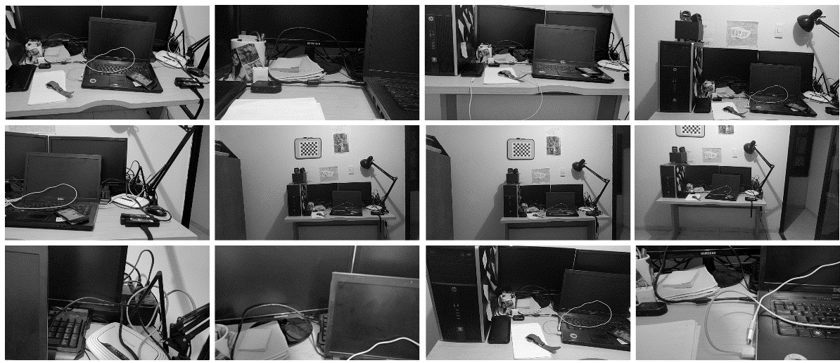
Fig. 8a shows images captured using the LG Nexus 5X smartphone, which describe a circular motion using a monopod support. The smartphone and the support were moved by hand along a circular trajectory painted on the ground with a 2,2 m radius. As observed in Fig. 8a, this test was performed indoors in a semi-structured environment. Fig. 8b shows the trajectory estimated by EVP in red, as well as the ground truth in blue. Additionally, the X and Y estimated position errors are depicted in Fig. 8c.
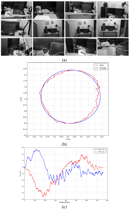
Figure 8: a) Some images obtained from the smartphone’s point of view when performing the circular trajectory; b) circular trajectory estimated by EVP in red and ground truth in blue; c) trajectory error
By observing these figures, it can be seen that the EVP-estimated trajectory is very similar to the ground truth, which shows promising results in estimating the smartphone’s trajectory indoors. At the very beginning, there is a high cumulative error, which is reduced along the trajectory, thanks the local bundle adjustment methods implemented in ORB-SLAM. This is also shown in Fig. 8c, where the XY error graphs have noticeable deviations in the initial part of the circular path. In this test, the root mean square error along the estimated trajectory was 0,166 m.
Fig. 9a shows images captured from the drone’s point of view during the open field test. This flight took place in the football field of Universidad del Valle, Cali, Colombia, covering an area of approximately 27 x 28 m. It is worth noting that the drone was not flying autonomously; it was manually controlled. As it can be observed in Fig. 9a, the captured images are low-textured, which poses a serious challenge for the position estimation algorithm implemented into the EVP software tool. Additionally, these images show the worst-case scenario. The ground truth in this test was obtained using a GPS-RTK system with an accuracy of 0,5 m. However, GPS-RTK systems do not have a high sampling frequency in comparison with the ORB-SLAM implemented into the EVP software tool.
Fig. 9b shows the resulting trajectory in the open field test in blue, as well as the GPS-RTK positioning in red. This Figure shows a closed trajectory which starts at approximately (-22,5 m, 10 m), since the GPS- RTK base station was located at (0, 0). In general, the software-estimated trajectory has a similar shape to the GPS-RTK trajectory. However, the last parts of these trajectories differ from each other due to the cumulative errors in the EVP-estimated trajectory, since the images taken from the drone’s point of view are very homogeneous and low-texture. Therefore, perceptual aliasing is high. This is a tough situation that many SLAM solutions cannot solve without combining other types of sensors. Also, in Fig. 9c, an error plot is depicted. This error plot corresponds to the cumulative error in X and Y along the trajectory. By using these readings, the root mean square error of the whole trajectory was 2,8 m, which is less compared with common positioning errors in GNSS mobile networks [22].

Figure 9: a) Some images obtained from the drone’s point of view when performing this trajectory; b) trajectory in open field estimated by EVP in blue, and ground truth obtained from GPS-RTK in red; c) Trajectory error vs. number of measures over time
The third test was performed in the Engineering Department’s small square at Universidad del Valle. In this test, images with a richer texture, in comparison with the second test, were acquired (Fig. 10a). This test covered an area of approximately 27,5 x 9 m. Again, the drone was not flying autonomously.
Fig. 10b shows the estimated trajectory computed by the EVP software tool in blue, and the ground truth using GPS-RTK in red. The quadcopter starts flying in the bottom right corner, and then it moves right. Fig. 10b shows a reduction in the estimation error, as observed in Fig. 10c. Again, due to cumulative error, the upper section in Figure 10b shows an increase in the relative position error.
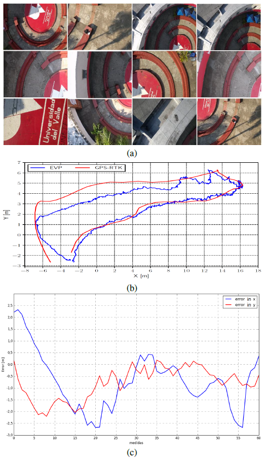
Figure 10: a) Some images obtained from the drone point of view when performing this trajectory; b) Trajectory along the roundabout of Engineering Faculty estimated by EVP in blue, and ground truth obtained from GPS-RTK in red; c) Trajectory error Vs. number of measures over time
In general, the EVP-estimated trajectory has a similar shape in comparison with the GPS-RTK trajectory. Using the error plots in Figure 10c, the root square error of the entire trajectory was computed, and it resulted in 1,4 m. This improvement was due to the richer image texture used by EVP to compute the drone’s position. In these situations, the ORB-SLAM approach can estimate better relative drone positions in comparison with the second test described above.
The related works show quantitative results that can be compared with the results obtained in this work. In [6]¸, the authors report tests in an indoor area of 3 x 4 m with localization errors of up to 0,0127 m. Additionally, they perform outdoor tests over a 180 m path with localization errors of up to 2,2m. In [9], the authors perform an indoor test over a 12 m path with localization errors of up to 0,84 m. In [11], the authors report localization errors of up to 35% of a path performed in an outdoor area of 250 x 150 m. In [10], the authors perform an indoor test in an area of 39 x 21 m with localization errors of up 10 m. In [16], the authors report results with localization errors of up to 2,8 m using tests in an indoor area of 15 x 8 m. In [8], the authors report results of localization errors of up to 0,148 m in an area of 3 x 4 m, and errors of up to 1,7% in indoor navigation. More relevant results are presented in [13], where the authors perform indoor tests in rooms with area of 11 x 5,5 m. The tests reported localization errors of up to up 0,3 m. Also in [17], localization errors of up to 2,6 cm in outdoor paths of up to 15,5 m is reported.
Considering the quantitative results described above, the most accurate results correspond to tests performed indoors and in small areas (errors of up to 0,3 m). Furthermore, tests over large areas or large non- closed paths have high localization errors (up to 10 m or 35% of the path length). In this work, indoor tests reported localization errors up 0,166 m in an area of 15 m2. Additionally, localization errors of up to 2,8 m were reported in a football field with low-texture information and covering an area of 25 x 27,5 m. The test performed in the Engineering Department square reported localization errors of up to 1,4 m in an area of 23 x 8,5 m. Therefore, considering the quantitative results obtained, EVP is a software tool that outperforms the reviewed results. EVP is an option to keep in mind in outdoor applications that need position estimation using vision sensors in GPS-denied environments.
Conclusions
In this work, the EVP software tool was presented. It was developed in two parts: the EVP base station and the EVP mobile app. In the EVP base station, users can configure the flight parameters, the ORB-SLAM parameters to estimate the drone’s position, and the communication link with the drone to receive the remote captured images and telemetry data; as well as visualizing the drone’s estimated position. In the EVP mobile app, users can configure the network parameters to communicate data to the EVP base station, as well as enabling the position estimation module and receiving estimated drone position from the EVP base station.
The position estimation method used was the ORB-SLAM for monocular cameras. Using this implementation, the EVP software tool does not need any artificial landmarks in the environment nor calibration patterns to track and estimate the drone’s position. Additionally, the EVP software tool does not need any previous knowledge of the environment to estimate the drone’s position in space using 6DOF. However, according to the tests performed and their results, it is very important to have high-textured images of the environment to obtain good position estimation results.
The EVP software tool was tested using three different experiments: first, using the smartphone only, and describing a circular indoor known trajectory; second, an open field test was performed in the main football field of Universidad del Valle; and third, another field test in the Engineering Department’s small square at Universidad del Valle. In the first experiment, the EVP software tool obtained an RMS error of up to 0,166 m in comparison with a ground truth circular trajectory of 2,2 m diameter painted on the ground. In the second and third experiments, the EVP software tool obtained an RMS error of up to 2,8 m and 1,4 m, respectively, in comparison with a ground truth trajectory using GPS-RTK. The RMS error in the third experiment was lower in comparison with the second field experiment, since images reported from the drone are richer in texture. These quantitative results were compared with those reviewed in the literature. As a result, EVP is an option to keep in mind in outdoors applications that need position estimation using vision sensors in GPS-denied environments.
Finally, future works include merging the image data with inertial sensors to adjust and reduce position estimation errors due to oscillations or sudden motions during flight. Also, the EVP position estimation could be completely implemented into the smartphone. In this way, the communication load due to continuous image transmission from the drone to the base station will be minimized, which enables the use of this kind of solutions in real-time applications.
References
License
Copyright (c) 2021 Eval Bladimir Bacca Cortes, Julio Urbano-López, José Buitrago-Molina

This work is licensed under a Creative Commons Attribution-NonCommercial-ShareAlike 4.0 International License.
![]()
From the edition of the V23N3 of year 2018 forward, the Creative Commons License "Attribution-Non-Commercial - No Derivative Works " is changed to the following:
Attribution - Non-Commercial - Share the same: this license allows others to distribute, remix, retouch, and create from your work in a non-commercial way, as long as they give you credit and license their new creations under the same conditions.

2.jpg)