DOI:
https://doi.org/10.14483/23448393.16903Publicado:
2020-10-05Número:
Vol. 25 Núm. 3 (2020): Septiembre - DiciembreSección:
Sección Especial: Mejores artículos extendidos - WEA 2020Design of a Troubleshooting Digital Test Bench for the Beechcraft King C-90, 200, B200, 300 and 350 Aircraft GCU
Diseño de un banco digital de pruebas para solución de problemas en la GCU de las aeronaves Beechcraft King C-90, 200, B200, 300 y 350
Palabras clave:
Aeronautics, avionics, aircraft, beechcraft King, GCU, test bench, troubleshooting (en).Palabras clave:
Aeronáutica, aviónica, aeronave, Beechcraft King, GCU, banco de pruebas, soluci´on de problemas (es).Descargas
Referencias
FlightSafety International, “King Air series B200 ATA 24 Manual”, FlightSafety International, 2014.
T. A. Lima, G. Lynn, P. Barber, J. Churchill and K. Dalphonse, “Method and apparatus for automatically testing and evaluating electric generator sets”. [Online]. Available: https://patents.google.com/patent/US5949247A/en?oq=US5949247A
J. M. Bourgeois, B. Cantin, D. Fournier, F. Leonard and Y. Roy, “Detección, localización e interpretación de una descarga parcial”. [Online]. Available: https://patents.google.com/patent/ES2372021T3/es?oq=ES2372021T3
A. P. Goldstein and M. Kearney, “Know when to fold ‘em: An empirical description of risk management in public research funding”, Research Policy, vol. 49, no. 1, 2020. https://doi.org/10.1016/j.respol.2019.103873
H. Ahn, H. Kim and H. L. Choi, “Integrated Risk Management Method Development for Multiple Aerospace Projects Using a Single Index Expression”, International Journal of Aeronautical and Space Sciences, vol. 19, no. 4, pp. 1052–1062, 2018. http://doi.org/10.1007/s42405-018-0092-5
C. Cabrera, F. Garay, D. Contreras and O. Gómez, “Modelo para el desarrollo de proyectos de innovación en tecnología para la aviación: Caso de estudio banco de pruebas digital para las pruebas caza fallas de la GCU de la aeronave Beechcraft King C-90, 200, B200, 300 y 350”, acceptance letter, 2020.
P. J. Rojas, “Doctrina Damasco: eje articulador de la segunda gran reforma del Ejército Nacional de Colombia”, Revista Científica General José María Córdova, vol. 15, no. 19, pp. 95-119, 2017. https://doi.org/10.21830/19006586.78
FlightSafety International, “King Air series B200 ATA 74 Manual”, FlightSafety International, 2019.
D. Wyatt, Aircraft Electrical and Electronic Systems. Burlington: Butterworth-Heinemann, 2009. https://doi.org/10.4324/9780080942971
P. Savioz and E. Sannemann, “The concept of the integrated innovation process”, in PICMET ’99: Portland International Conference on Management of Engineering and Technology. Proceedings Vol-1: Book of Summaries (IEEE Cat. No.99CH36310), Portland, July 1999.
Cómo citar
APA
ACM
ACS
ABNT
Chicago
Harvard
IEEE
MLA
Turabian
Vancouver
Descargar cita
Recibido: 1 de junio de 2020; Revisión recibida: 31 de agosto de 2020; Aceptado: 15 de septiembre de 2020
Abstract
Context:
The Colombian Army’s First Aircraft Maintenance Battalion must periodically test the performance of Generator Control Unit (GCU) on its Beechcraft King Air aircraft, which compels the operator to assume uncomfortable and non-ergonomic physical positions. This article proposes the use of a portable digital troubleshooting test bench for these units that facilitates the taking of measurements, the interpretation of the acquired information, and the technical reports.
Method:
The Integrate, Innovation, Process model (IIP) for the development of aviation technology innovation projects was used to design the test bench. Then, its functional modules were defined, and voltage and impedance measurement devices, an internal report storage system, and the user interface were included. Tests were conducted together with technical operators on the available Beechcraft King C-90, 200, B 200, 300, and 350 series aircraft. Finally, a technical report was elaborated to validate the test bench results.
Results:
The number of operators required to carry out the tests was reduced from four to one. The digital test bench only requires the connection of measurement harnesses by the operator, so it allows an improvement in ergonomics for the personnel. Using the bench, the review and evaluation time of the GCU was reduced from 120 minutes to 26 minutes, which implies an 86,66% decrease in fuel consumption.
Conclusions:
By using the digital troubleshooting test bench, the number of operators needed and the checkup and assessment times of the GCU were reduced, which means a decrease in fuel expenses. Its ease of transportation allows aircraft to be checked outside the Maintenance Battalion hangars, but the implementation of a USB port to store the reports should be considered.
Keywords:
Aeronautics, avionics, aircraft, beechcraft King, GCU, test bench, troubleshooting..Resumen
Contexto:
El Batallón de Mantenimiento de Aviación No. 1 del ejército colombiano debe realizar pruebas periódicas del funcionamiento de la Unidad de Control de Generado en sus aeronaves Beechcraft King Air, que obligan al operador a asumir posiciones físicas incómodas y no ergonómicas. Este artículo propone el uso de un banco portátil digital de solución de problemas para estas unidades que facilite la toma de medidas, la interpretación de la información adquirida y la generación de informes técnicos.
Método:
Para el diseño del banco de pruebas se usó el modelo integrado Integrate, Innovation, Process (IIP) para el desarrollo de proyectos de innovación en tecnología para la aviación. Posteriormente, se establecieron los módulos funcionales del banco y se incluyeron dispositivos de medición de tensiones e impedancias, el sistema de almacenamiento interno de informes y la interfaz de usuario. Se realizaron pruebas junto con operadores técnicos en las aeronaves disponibles de la serie Beechcraft King C-90, 200, B 200, 300 y 350. Finalmente, se elaboró un informe técnico de validación de los resultados del banco.
Resultados:
Se redujo la cantidad de operarios necesarios para el desarrollo de las pruebas de cuatro a uno. El banco de pruebas digital solo requiere la conexión de arneses de medida por parte del operador, lo que permite una mejora en la ergonomía del personal. Con el uso del banco se disminuye el tiempo de revisión y valoración de la GCU de 120 minutos a 26 minutos, lo cual, a su vez, representa una disminución del 86,66% en consumo de combustible.
Conclusiones:
Con el uso del banco de pruebas digital de solución de problemas, se redujo la cantidad de operarios necesarios y los tiempos de revisión y valoración de la GCU, lo cual representa una disminución en los gastos en combustible. Su facilidad de transporte del banco permite revisión de las aeronaves fuera de los hangares del Batallón de Mantenimiento, pero se debe contemplar la implementación de un puerto USB para almacenar los informes.
Palabras clave:
Aeronáutica, aviónica, aeronave, Beechcraft King, GCU, banco de pruebas, solución de problemas..Introduction
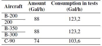
Nowadays, the First Aircraft Maintenance Battalion (BAMAV No. 1) must periodically test the performance of the Generator Control Unit (GCU) of its Beechcraft King Air B200 series aircraft (BB006, BBT002, BB1152, BB 1615, B-300-FL 713 B350, FL 454, and C-90). These tests are based on the protocols defined within the maintenance manual for this series’ ATA 24 [1]. This manual specifies the use of a test bench that allows the operator to take 16 measurements of voltage and resistance at different electrical points of the GCU. The test requires the aircraft’s engines to be at 70% power and the GCU to be connected to the test bench in order to take measure each of the 16 channels. The test takes approximately two hours (the average time it takes the operator to measure the voltage and resistance), where the engines must be cycled on and off until the end of the test, which means high fuel costs. Table I shows the reported fuel consumption values in GCU tests.
*These values correspond to the records of the First Aircraft Maintenance Battalion when testing the King 200, B200, 300, 350 and C90 aircraft.
Table I: Reported fuel consumption in GCU fuel tests.
Data collection from each test is carried out according to the pre-established format for GCU testing of the BAMAV No. 1, and the information is stored in each aircraft. For taking measurements, the bench integrates a multimeter with an annual calibration certificate, where the operator selects the unit of measurement and the option of measuring voltage or resistance. Due the importance of GCU troubleshooting tests, the Military Aviation Research Group of the Army Aviation School (ESAVE) and the technical personnel of the BAMAV No. 1 identified the following difficulties making the troubleshooting protocol measurements for the GCU of the Beechcraft King Air aircraft:
-
the GCU unit of the aircraft is in a difficult access location, since it is necessary to lift part of the aircraft floor to reach it;
-
the test bench proposed by ATA 24, forces the operator to assume uncomfortable and nonergonomic positions with the use of the multimeter for measurement;
-
channel selection in the GCU troubleshooting bench and multimeter operation requires the operator leave the unit’s location, forcing the support of an additional technician to perform the test; and
-
the approximate time for carrying out the test largely depends on the agility and maneuverability of the measuring instrument by the operator.
Therefore, the design of a digital portable bench was proposed for the GCU troubleshooting tests of this aircraft series. This device would automatically select channels, test the GCU, interpret the acquired information, and generate technical reports of the tests, with the support from a server belonging to the Aircraft Maintenance Battalion. The bench reduces the fuel consumption, time, and personnel required to carry out the test, in addition to improving the technical personnel’s occupational health and safety by standardizing and optimizing maintenance processes and improving the traceability of GCU inspection processes.
Technological search
To find development references for this type of test bench aside from those by the ATA 24 manual, a technological search was carried out with the help of the Intellectual Property department of the Directorate of Science and Technology of the Colombian National Army. The search was carried out in the main databases for consulting patents and projects, which contains the databases of the Colombian Superintendence of Industry and Commerce, the United States’ USPTO, the World Intellectual Property Organization (OMPINIPO), the European companies Epoline and Espacenet, and the Chinese SIPO GOV. As a result, no pre-exsisting products or projects were found. However, this section describes some of the technological developments that have been implemented to solve GCU problems in this aircraft series.
Testing and evaluating electric generator sets
The Method and Apparatus for Automatically Testing and Evaluating Electric Generator Sets with patent number US5949247A consists of a fault detection system through the consumption detection and monitoring under the voltage and current standards in a feedback system where the information is analyzed. Then, when the the normal operating parameters of the generator deviate from the standard and enter a zone of possible risk or malfunction, the system determines what the failure could be from the variable that reported the deviation [2]. This bench is useful for AC systems related to electric generators, but it does not directly involve the GCU; it depends on operator control signals, and its operability relies on under digital signal. Furthermore, its sampling frequency depends on the maximum frequency within the generator system. This patent lacks control points or power lines that handle 3 signals to analyze (impedances, voltages, and currents).
GCU Test Box in the ATA 24 KING 200 Aircraft Maintenance Manual
The ATA 24 Beechcraft King C-90, 200, B200, 300, and 350 aircraft maintenance manuals proposes a test box to perform the GCU troubleshooting test. It has a contact knob with which each of the 16 measurement points of the control unit can be selected. The operator, aided by a multimeter, and according to the measurement procedure, must select the variable, start the motors, operate on and off cycles, and take the measurement on the test box. Using this test bench, the estimated proceduretime is 2 hours with engine ignition cycles at approximately 70% power. Once the measurements have been carried out, the information acquired is analyzed by a specialized technician (different from the operator) who determines whether the component is in operating conditions or if, on the contrary, it must be replaced and repaired. The voltages, currents, and impedances table, as well as the GCU verification procedure are set out in the ATA 24 aircraft maintenance manual [1]. However, the conditions under which the test is performed and its times make it necessary to develop a test bench for the GCU to facilitate the procedure.
Partial discharge detection, location, and interpretation
This invention registered under patent number ES2372021T3, a device for the detection, location, and interpretation of a partial electric shock. To this effect, it is made up of 2 measurement probes and a synchronization probe, where the electrical equipment is diagnosed from the phase of the detected signals, which allows assessing damage to the electrical insulation, among other considerations [3]. Although the project requires a control unit and use under certain conditions, it could be adapted to aeronautical electrical systems. However, this device was not proposed in the context of a troubleshooting bench, and it is therefore not applicable for use in the Beechcraft King aircraft’s GCU.
The electrical system of the Super King Air 200 aircraft
The Super King Air 200 Series aircraft are a family of twin turboprop aircraft designed and produced by Beechcraft. Its direct current electrical system is made up of two generators connected in parallel, a battery, a panel of DC components, and a connector for an external plant, as seen in Fig. 1. It should be noted that, as part of the continuous fleet modernization by the National Army the inverters that are part of the manufacturer’s original aircraft were removed. The aircraft’s Figure 1. Electrical system of the Beechcraft King Air [1#093; primary electrical system is a 30 VDC generator system, regulated to 28,25 _ 2,5 volts, and it has a capacity of 250 amps to supply current to the main distribution bars (hot battery bus, main battery bus, left generator bus, right generator bus, isolation bus, No. 1 dual fed bus, No. 2 dual fed bus, No. 3 dual fed bus, No. 4 dual fed bus). The airship’s electrical diagram can also be seen in Fig. 2.
Figure 1: Electrical system of the Beechcraft King Air [1]
Figure 2: General electrical diagram of the Beechcraft King aircraft [1]
Generator Control Unit (GCU)
The Engine-Generators are controlled by the GCU. These units are located in the front of the aircraft, specifically below the main mast aisle. During normal operation, each voltage regulator monitors the engine-generator’s voltage output and controls the produced electromagnetic field to maintain a constant load under variable operating conditions such as changes in speed, voltage, and temperature of each motor.
Among the main functions of the GCU are:
Relay control.
Regularly measuring and controlling voltage in the generators.
Checking the connection and disconnection in parallel between generators.
Measuring reverse currents.
Relay control and voltage regulation
The GCU monitors the starter motor output voltage and controls the coils excitation fields, thus maintaining a constant voltage load that allows supplying electric current to each component under variable engine operating conditions. For the control unit to regulate the motors, it must be maintained at a residual voltage. This is obtained from generator terminal B and must be between 0,5 to 1,2 VDC.
Control of parallel connection and disconnection between generators
It is carried out with all the input terminals of all the connected devices coincide with each other, as well as their output terminals. The operation of an equalizer circuit is necessary to distribute equitably all loads connected to the aircraft. The voltage regulators are interconnected and employ the LH and RH relays in parallel, energized by the reverse current relays.
Reverse current relays
When the generator fields are excited for some reason or when the generator is below the minimum point and positive charge cannot be maintained, the generator requests, through the reverse current relay, a load to the aircraft busbar “Main Batt Bus”, which is connected to the battery. This reverse current relay is a normally open electrical device that, being magnetically switched, allows the passage of current from the battery to the aircraft components. However, were the above to happen, the aircraft would enter an emergency condition and have to land immediately. The measurement of reverse currents allows the protection of the connection line of the generators. Its function is to measure the voltage and current that pass through the line. If the voltage is high (greater tan 32,5 VDC), this will open the internal contact of the relay that will disconnect the generator.
Methodology: bench design
The test bench design and development were carried out according to an Integrate, Innovation, Process model (IIP) for the development of aviation technology innovation projects: which involves active project management for risk mitigation in a research project portfolio [4]. Thus, as science and technology have become a trend of convergence in the aeronautical sector, projects have become large, complex and which is why they must be rapid, reasonable, and objective to be successful [5]. This model makes use of the activities provided by standards and methodologies for projects that seek to generate innovation in products for the aeronautical sector. To this effect, the 5 phases of the model, which can be seen in Fig. 3, were used [6].
Figure 3: IIP Integrated Model Phases for the development of aviation technology innovation projects [6[
The model was applied correctly in every phase of the study case project, and its use assured quality procedures with the implementation of its different tools. The evaluation of the model also verified product innovation, which was a structural focus in this case. Therefore, the model can be considered as an integrated IIP model that goes beyond product development because it permits the generation of new knowledge and new business models in advanced maturity phases, as well as in future commercialization.
Idea identification
The BAMAV No. 1 and ESAVE have implemented innovative practices in the development of their activities, which is part of the articulating axis of the Colombian National Army’s institutional transformation plan [7]. Therefore, no effort has been spared in improving maintenance processes, identifying the parts of aircraft engines considered considered to have a high turnover in the warehouse. For this specific exercise, the aircraft’s GCU, the spark plugs, and the ignition elements subsystem are individualized [8], [9]. The identified ideas must supply the need to optimize maintenance processes, automating the GCU troubleshooting tests in compliance with those in the ATA maintenance manual.
Product definition
In this phase, a conceptual approach to the GCU operation and its troubleshooting test protocols in the maintenance manuals was set, as well as test requirements and developer designation. Likewise, a review was carried out on the manufacturer’s documentation and the experience of maintenance personnel of BAMAV No. 1 provided information on the tests that are generally carried out on the aircraft. Additionally, a conceptual definition of the product, the determination of its functional (FR) and non-functional (NFR) requirements, and its formalization were developed. Among these were automation (FR), availability (FR), security (NFR), connectivity (NFR), resistance (NFR), aesthetics (NFR), portability (NFR), ergonomics (NFR), adaptability (FR), and maintainability (NFR).
Product design
For the bench design, the Quality Function Deployment (QFD) and Design for Excellence (DfX) tools were used. Then, a conceptual design was made to lay out the required product, and the system was decomposed to relate each hardware, software, and structure requirement [6].
Conceptual design
The conceptual design contemplated the operation sequence (start, test, stop), understanding the function of each operation and the actions that the elements within the bench would perform. First, we proceeded to understand the test box circuit diagram for the GCU (shown in Fig. 2) and the wiring diagram available in the maintenance manual for the aircraft’s ATA 24, with which the number of channels to be measured was determined, as well as the type of contact to be used for channel selection and connection of the measurement device.
Design selection
The design was selected by means of the Pugh method and by comparison with the planned designs, this under the detailed analysis by the group of experts belonging to BAMAV No. 1 and ESAVE.
Detailed design
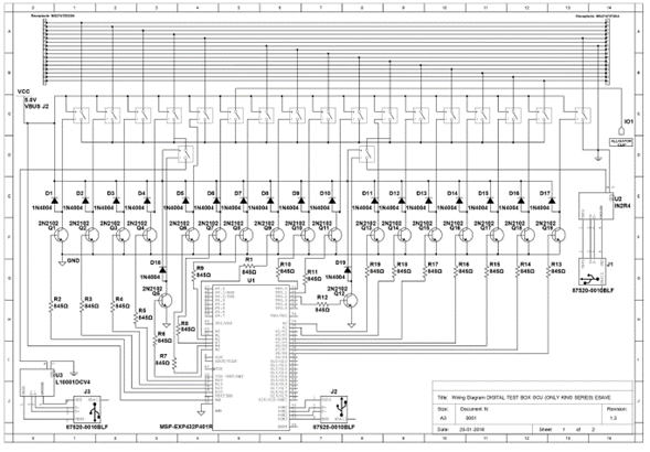
In accordance with the information above, the parameters and electrical characteristics that the digital bench should carry were established, and the type of relay that replaces the manual selection of channels by the operator was selected. Likewise the type of microcontroller that controls the opening or closing of measurement channels was determined; the EXP432P401R microcontroller was selected, and two independent channels were established for voltage and resistance collection, according to the procedure defined in the GCU maintenance manual. The layout of the circuit diagram can be seen in Fig. 4.
Figure 4: GCU troubleshooting bench circuit diagram.
It is necessary for the bench’s control interface to take the voltage or resistance data and interpret and compare them with the standards for each aircraft. Therefore, 2 independent measurement Figure 4. GCU troubleshooting bench circuit diagram. instruments were one for voltages, which handles the UART, RS232, RS485, USART communication protocols; and another for impedances, compatible with the LABVIEW software measurement interface modules, and preferably with POE power in the case of using a TCP/IP 10BT, RJ45 connection. The power system was established for both the computer that has the bench’s control interface and the hardware that has the electronic circuit in charge of channel selection, in order to take measurement, and communicate with the control interface, whose limit is the current capacity delivered by the computer USB port that has the user interface, limiting the system to 5 V and a maximum consumption 500 mA.
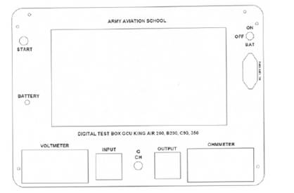
For the structural design, the minimum required space that the bench should have was defined, taking into account the electronic circuit (hardware) and the control interface dimensions. The design was defined under a Computer Aided Design (CAD) environment of the box containing the devices and supporting the ports and harnesses for connection to the GCU. This design can be seen in Fig. 5.
Figure 5: Detailed design bench front.
Design evaluation
The design was evaluated through ESAVE’s model contemplated for the development of aviation technology innovation projects , where the DfX is specified as a tool for evaluating quality and decomposition of the product through design for manufacturing (DfM) [6].
Development
The construction phase included the structure manufacture, hardware, software, and the integration of these two through the previously defined communication protocol.
Hardware development
The previously designed elements such as the box containing the test bench, the electronic board, and the power module were integrated into the hardware development. The electronic board and the computer that contains the bench’s control interface were made based on the previous structural design. Likewise, the structural manufacture was limited to the Aircraft Battalion body of technicians and engineers observations, concerning the material, protection index, and thermal and electrical insulation. All hardware was developed by engineers of the research group in military aviation, which belongs to ESAVE. It was necessary to design four test bench models and evaluate them using the Pugh method and innovation indexes (automation, availability, security, connectivity, resistance, aesthetics, portability, ergonomics, adaptability, and maintainability).
Software development
In this stage, the communication protocol programming on the microcontroller (UART) was developed, which determines the measurement channels using a reception code for selection. This code is transmitted by the portable electronic device. Once the communication protocol was determined, and the microcontroller in charge of interpreting and executing the activation of the 16-channel relay (one at a time) and the measurement (voltages or impedances) was selected. It was developed in C ++ language, the software that takes care receiving the communication frame, according to the protocol table, where the message type is identified for the activation or closure of the different relays, as well as the name or numerical hardware identification in charge of executing the orders and the software that issues the control sentences. For the GUI development, National Instruments’ popular LabVIEW® development software package was used for testing, measurement, and control applications.
HW/SW integration
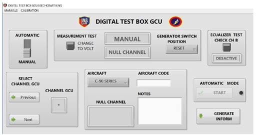
The integration was performed with the code installation on the mobile device of the user interface that allows controlling the test sequence, data acquiring and processing, and saving the reports. This interface that includes the channel manual selection and measurement type, in case the bench operator needs to know specifically the voltage or impedance of a specific channel, as well as an automatic option that tests all 16 channels according to the procedure established in aircraft maintenance manual, section 24-00-31. In the software, a database must be integrated that includes the standard measurement parameters of each channel, both for voltage and impedance, where the obtained measurement is compared with the standard measurement for each channel to determine the GCU unit use or replacement, detailing the channels result, aircraft identification, and test date and time. At the troubleshooting test end, the software delivers a report with the information previously described in PDF format. The final graphical interface can be seen in Fig. 6.
Figure 6: Graphical User Interface.
Structural assembly
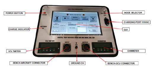
The structure and materials of the bench were approved by the Aircraft Battalion No. 1. In this stage, the assembly of harnesses, connectors, electronic board, and the computer was carried out. At first, it was necessary to carry out the fastening of the connectors, harnesses, power button, and 110 VAC power input, followed by the installation of the electronic board and the computer that supports the control interface. Fig. 7 shows the result of the assembly.
Figure 7: Test bench assembly (final result)
Validation
For the validation process, the prototype was provided to BAMAV No.1 so that tests could be carried out, together with technical operators, on the available Beechcraft King C-90, 200, B 200, 300 and 350 series aircraft. The maintenance manager was asked to elaborate a technical report to Figure 7. Test bench assembly (final result) validate the bench results, and he was asked to make tests for troubleshooting with the test bench established by the ATA manual, in order to compare resource use and time between the created bench and the current measurement protocol. The approval criteria were:
-
Field tests: a test plan was made with the Beechcraft King C-90, 200, B 200, 300 and 350 aircraft GCU under operating conditions in maintenance shops. To check this, the maintenance personnel was allowed to make final adjustments and correct the generated noise in the signals and other disturbances. Also, conducting the tests serves as an instrument to verify compliance with the requirements set out in the initial phase.
-
Test results analysis: the sequential behavior and the individual restart of each test allows visualizing the impedance and voltage values. As evidenced by the maintenance manager technical report, this ensures the validity of each test.
-
Innovation analysis: using the integrated IIP model made it possible to verify the innovation of the product. In this case, the project had a structural approach, going beyond product development, thus allowing the generation of new knowledge and the optimization of organizational processes [10]. The innovation indexes evaluated was the process automation, availability, security, connectivity, resistance, aesthetics, portability, ergonomics, adaptability, and maintainability.
Results and discussion
Once the troubleshooting digital test bench for the Beechcraft King C-90, 200, B 200, 300 and 350 aircraft’s GCU was developed and approved by the Department of Avionics of the First Aircraft Maintenance Battalion, the development was delivered to BAMAV No. 1, for certification and implementation.
Channel isolation and channel selection
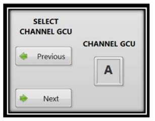
The tests confirm that the test bench measurement channels are duly isolated from each other, allowing the measurement to be taken on each channel independently without affecting or altering the others. Moreover, the equalizer test in the active state places the channels G and E in direct contact (impedance equal to 0,00 ohms, ruling out the measurement line impedance) as specified for this test in the ATA 24-30 manuals. [1]. Table II shows the impedance values greater than 10 M for each of the channels when the references (REF) are A, B, C, D, E, F, G, and H. The rest of the channels must be in open circuit. The Fig. 8 shows a measurement channel “A”; once in the ConFg section, it establishes a short circuit between the “G” ground ports and the “A” port of the connector.
Figure 8: GCU troubleshooting bench, measure channel “A” example
aThese values correspond to the test channels (A, B, C, D, E, F, G, H, J, K, L, M, N, P, R, S). bThis column corresponds to the impedance test channels (A, B, C, D, E, F, G, H) labeled as REF.
Table II: Impedance values in voltage test (channels A, B, C, D, E, F, G, H).
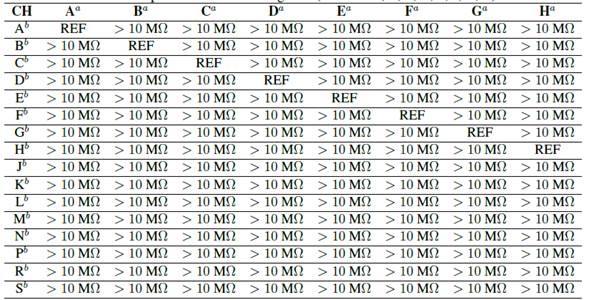
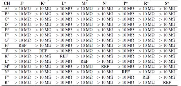
Table III shows the impedance values greater than 10 M for each of the channels when the references (REF) are J, K, L, M, N, P, R, and S. The rest of channels must be in open circuit.
Table III: Impedance values in voltage test (channels J, K, L, M, N, P, R, S).
Voltage and impedance measurement tests
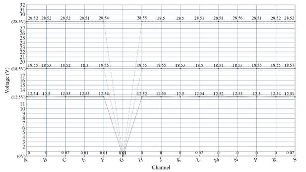
The ATA manual states that the voltage measurement ratio for the GCU troubleshooting process is 1% or 0,01 V. According to this parameter, the test bench complies with the measurement (0 V,12,5 V, 18,5 V, 28,5 V) and resolution parameters established by the manufacturer. Additionally, the voltage measurement acquired by the bench is compared with a voltage source (10894 calibration certificate (MPL3303 S / N D02200602982)) with a digital voltmeter (10794 calibration certificate (ET-2907 S / N 80200239)), with calibration certificates of less than one year, thus validating that the measurement is within the expected real parameters. In Fig. 9 the control graph of the voltage results from taking protocol for 4 measurement standards clearly the Ground Channel G has 0 V.
Figure 9: Voltage result for standard values (0 V, 12,5 V, 18,5 V, 28,5 V)
Resource use (time, personnel, fuel)
Under laboratory tests and aircraft impedance reading tests, the GCU review can be carried out in just 5 minutes, which, in addition to the time it takes to generate an engine cycle (engines at 70 %, on and off), executes the entire test in just 26 minutes, with a time reduction of 81,6 %, requiring only one technician to connect the bench and run the test. The reduction in fuel consumption when performing the GCU troubleshooting test is directly related to the reduction in time, which allows obtaining a final consumption of JET A1 fuel of 43 gallons (average according to the aircraft analogue indicator), which represents an 86,66% decrease in fuel.
Technical concept
Considering the technical concept of BAMAV No.1 regarding the prototype validation and according to the results, it is determined that the troubleshooting digital portable test bench for the Beechcraft King aircraft’s GCU (Generator Control Unit) is a functional and fully operational prototype for the troubleshooting procedure ordered by the aircraft series’ maintenance manual.
Financial evaluation
The approximate development cost is approximately US$ 3108. With the conventional measurement process, approximately 246,4 gallons of Jet A1 fuel are used, which corresponds to US$ 377, whereas, with the developed test bench, the consumption is 43,12 gallons (US$ 65). Therefore, it is economically convenient to use the test bench maintenance activities.
Conclusions
The procedure for taking measurements on the 16 lines of the GCU connector established by the maintenance manual of the series of aircraft in question involved uncomfortable and non-ergonomic maneuvers for the technicians. Thanks to the new digital test bench development, it only requires the connection of measurement harnesses by the operator, significantly improving the comfort of the technician when carrying out this type of tests.
Once the digital bench completes the troubleshooting test, a report is generated comparing the result obtained with the standard established for the aircraft for each of 16 channels, which facilitates and allows the operator to determine which channel is defective and the voltage deviation or resistance as a detected fault result. As a suggestion for future implementations or improvements to the developed bench, the the technical staff of the Maintenance Battalion recommends repositioning the HMI component to the front of the case, and enlarging the screen to 15 inches to facilitate the reading of the measurements manipulate the control interface more easily.
Due to the bench’s mobility, GCU reviews can be carried out outside the Maintenance Battalion hangars (operations area). However, it is recommended to implement a USB port in the future, to store the final report obtained through the bench in an easily transportable magnetic medium, since the bench currently stores this information on its local disk and in the cloud when an internet connection is available.
Acknowledgements
Acknowledgment
This research was carried out thanks to the collaboration of the Aircraft Maintenance Battalion No. 1 and the Aviation School of the Colombian National Army, who contributed the resources for the development of the prototype, as well as the the maintenance technicians, who agreed to validate the test bench implementation. This project was funded by the National Army of Colombia, Department of Science and Technology, under internal code No. 118315.
Referencias
Licencia
Derechos de autor 2020 Fabian Steven Garay Rairan, Carlos Arturo Cabrera Arias, Ingrid Arango Calderón

Esta obra está bajo una licencia internacional Creative Commons Atribución-NoComercial-CompartirIgual 4.0.
A partir de la edición del V23N3 del año 2018 hacia adelante, se cambia la Licencia Creative Commons “Atribución—No Comercial – Sin Obra Derivada” a la siguiente:
Atribución - No Comercial – Compartir igual: esta licencia permite a otros distribuir, remezclar, retocar, y crear a partir de tu obra de modo no comercial, siempre y cuando te den crédito y licencien sus nuevas creaciones bajo las mismas condiciones.


![Electrical system of the Beechcraft King Air [1]](https://revistas.udistrital.edu.co/index.php/reving/article/download/16903/version/12666/17277/105188/0121-750X-inge-25-03-393-gf1.png)
![General electrical diagram of the Beechcraft King aircraft [1]](https://revistas.udistrital.edu.co/index.php/reving/article/download/16903/version/12666/17277/105189/0121-750X-inge-25-03-393-gf2.png)



2.jpg)


