DOI:
https://doi.org/10.14483/23448393.18495Published:
2022-01-04Issue:
Vol. 26 No. 3 (2021): September - DecemberSection:
Sección Especial: Mejores artículos extendidos - WEA 2021Un enfoque desde la ingeniería de software a una solución tecnológica de IoT y aprendizaje automático que permita monitorear y controlar las variables medioambientales en un cultivo de café
An Approach from Software Engineering to an IoT and Machine Learning Technological Solution that Allows Monitoring and Controlling Environmental Variables in a Coffee Crop
Keywords:
Internet of Things, machine learning, computer application, UML, static views, dynamic views, conceptual modeling, behavioral modeling (en).Keywords:
Internet de las cosas, aprendizaje automático, aplicación informática, UML, vistas estáticas, vistas dinámicas, modelamiento conceptual, modelado del comportamiento (es).Downloads
References
M. Rossainz-López, Diseño orientado a objetos, México D.F., México: Universidad Autónoma de Puebla, 2012.
B. Boehm, “A view of 20th and 21st century software engineering,” in 28th Int. Conf. Soft. Eng. (ICSE '06), Shangai, China, May 2006. https://citeseerx.ist.psu.edu/viewdoc/download?doi=10.1.1.97.4717&rep=rep1&type=pdf DOI: https://doi.org/10.1145/1134285.1134288
IEEE, IEEE Guide to Software Design Descriptions, Piscataway, NJ, USA: IEEE, 1993.
C. Larman, UML y patrones, Madrid: Pearson, 2003.
J. Rumbaugh, I. Jacobson, and G. Booch, El lenguaje unificado de modelado: manual de referencia, Madrid: Addison Wesley, 2000.
L. Ramírez, “Diseño de una arquitectura para redes de sensores con soporte para aplicaciones de detección de eventos,” Doctoral Thesis, Universidad Politécnica de Valencia, Valencia, Spain, 2012. https://riunet.upv.es/bitstream/handle/10251/15152/tesisUPV3764.pdf
N. D. Castro C, L. E. Chamorro F, and C. A. Viteri M, “Una red de sensores inalámbricos para la automatización y control del riego localizado,” Revista de ciencias agrícolas, vol. 33, nº 2, pp. 106-116, Aug. 2016. http://dx.doi.org/10.22267/rcia.163302.57 DOI: https://doi.org/10.22267/rcia.163302.57
K. E Kendall and J. E Kendall, Analisis y diseño de sistemas, Mexico D.F., México: Prentice Hall, 2011.
E. Rozic and S. Herzovich, UML y desarrollo de software orientado a objetos, México D.F., México: Universidad de San Andrés, 2016.
R. Yeh and P. Zave, “Specifiying Software Requirements,” Proc. IEEE, vol. 68, no. 9, pp. 1077-1085, 1980. https://doi.org/10.1109/PROC.1980.11806 DOI: https://doi.org/10.1109/PROC.1980.11806
B. Boehm, “Software Engineering,” IEEE Trans. Comp., vol. 25, no. 12, pp. 1226-1241, Dec. 1976. https://doi.org/10.1109/TC.1976.1674590 DOI: https://doi.org/10.1109/TC.1976.1674590
A. N. Camacho-Zambrano, “Herramienta para el análisis de requerimientos dentro de la pequeña empresa desarrolladora de software en Bogotá D.C.,” Undergraduate Thesis, Pontificia Univesidad Javeriana, Bogotá D.C., Colombia, 2005. http://hdl.handle.net/10554/7480
R. Pressman, Ingenieria del software un enfoque práctico, Bogotá D.C., Colombia: McGraw Hill, 2010.
E. J. Naiburg and R. A. Maksimchuk, UML For Database Design, New York, NY, USA: Addison-Wesley Publishing Company, 2001.
M. Fewler, UML Gota a Gota, México D.F., México: Pearson Educación, 1999.
C. Krall, “aprenderaprogramar.com,” https://bit.ly/3srfpe9 (accessed Apr. 10, 2021).
E. Kendall and J. Kendall, Analisis y diseño de sistemas, México D.F.: Pearson Educacion, 2011.
J. Schmuller, Aprendiendo UML en 24 horas, México D.F., México: Pearson, 2000.
Universidad Carlos III de Madrid, Modelado dinámico básico, Madrid, Spain: Universidad Carlos III de Madrid, 2018.
K. Cevallos, «Ingeniería del software,» https://bit.ly/3ah5xgw (accessed Apr 12, 2021).
How to Cite
APA
ACM
ACS
ABNT
Chicago
Harvard
IEEE
MLA
Turabian
Vancouver
Download Citation
Recibido: 15 de agosto de 2021; Revisión recibida: 27 de agosto de 2021; Aceptado: 15 de septiembre de 2021
Abstract
Context:
Software engineering allows us to approach software design and development from the practical application of scientific knowledge. In the case of this IoT solution and the machine learning approach to the monitoring and control of environmental variables in a coffee crop, it allows us to visualize certain artifacts of the system in their interaction with users and their behavior with other artifacts or devices that constitute a technological solution.
Method:
For this work, the application of software engineering from a conceptual approach and the behavior of the system is proposed. To meet these objectives, we decided to use the Unified Modeling Language (UML) in such a way that the most important components of the technological solution could be represented from a static perspective through the use case diagrams, as well as from a dynamic viewpoint through the sequence diagrams.
Results:
Through the application of the UML, it was possible to develop the conceptual and behavioral modeling of certain artifacts and components. This knowledge allowed identifying the interaction between physical components and devices (machine to machine) and human-machine interaction, that is,the relationship between users and the processes that make up the technological solution.
Conclusions:
Through software engineering, and more specifically the UML, we were able to establish the importance of knowing the different software artifacts that make up a system or application from a different technical and functional approach, while being able to collect valuable information about the behavior of certain system artifacts, as well as the interaction between users and processes.
Keywords:
Internet of Things, machine learning, computer application, UML, static views, dynamic views, conceptual modeling, behavioral modeling..Resumen
Contexto:
La ingeniería de software nos permite abordar el diseño y desarrollo de software desde la aplicación práctica del conocimiento científico. En el caso de esta solución de IoT y el enfoque de aprendizaje automático en el monitoreo y control de las variables medioambientales en un cultivo de café, nos permite visualizar determinados artefactos del sistema en su interacción con los usuarios y en el comportamiento con otros artefactos o dispositivos que integran una solución tecnológica.
Método:
Para el presente trabajo, se plantea la aplicación de la ingeniería del software desde un enfoque conceptual y del comportamiento del sistema. Para cumplir con estos objetivos se optó por emplear el lenguaje unificado de modelado (UML) de forma tal que se pudieran representar los componentes más importantes de la solución tecnológica desde una perspectiva estática a través de los diagramas de casos de uso y desde el punto de vista dinámico a través de los diagramas de secuencia.
Resultados:
Mediante la aplicación del UML, fue posible desarrollar el modelamiento conceptual y del comportamiento de ciertos artefactos y componentes. Este conocimiento permitió identificar la interacción entre componentes y dispositivos físicos (máquina a máquina) y la interacción hombre-máquina, es decir, la relación entre usuarios y procesos que componen la solución tecnológica.
Conclusiones:
A través de la ingeniería de software y más específicamente del UML, pudimos establecer la importancia de conocer los diferentes artefactos que componen un sistema o aplicación desde un enfoque técnico y funcional diferente, pudiendo recopilar información valiosa sobre el comportamiento de ciertos artefactos del sistema, así como de la interacción entre usuarios y procesos.
Palabras clave:
Internet de las cosas, aprendizaje automático, aplicación informática, UML, vistas estáticas, vistas dinámicas, modelamiento conceptual, modelado del comportamiento..Introduction
Many times, we have wondered why software engineering is so important today; we cannot ignore the potential growth of the software industry at a global level. But how can we define software engineering? Let us take some valuable definitions from experts on the subject. According to [1],software engineering is the study of the principles and methodologies for the development and maintenance of software systems.
In another definition given by [2], the author defines software engineering as the practical application of scientific knowledge to the design and construction of computer programs and the associated documentation required to develop, operate, and maintain them. This is also known as software development or software production. It is the application of a systematic, disciplined, and quantifiable approach to the development, operation, and maintenance of software, that is, the application of software engineering [3].
By analyzing the above, we can develop our own definition and establish that software engineering is actually a discipline or area that is responsible for generating a series of methodologies or guidelines to develop the life cycle of the software, regardless of the adapted or implemented methodology,but always seeking to comply with each of its phases or stages through deliverables or documentation that allows supporting the functionality or interaction of an artifact or system component with other components or roles of the same system or, in certain cases, with subsystems or external systems as needed.
More specifically, we want to delve into aspects such as conceptual modeling and system behavior while using the Unified Modeling Language (UML). According to [4], UML is a standard that has been adopted internationally by numerous organizations and companies to create schematics, diagrams, and documentation related to software development (informatic programs).
According to [5], UML is the combination of three different methodologies developed by its creators, who aim for the user to understand the reality of the implemented technology, as well as giving them the possibility to make decisions before investing large amounts of money and time in projects if they are not sure about their development, and much less in the construction of artifacts that will constitute said model.
Considering the above, we can conclude that UML is a standard for the construction of software models that allows knowing the operation of certain artifacts or components of a software development,as well as the interaction that said components or artifacts may have with the users of the system, with other devices or artifacts, with subsystems of the same system, or even with other external systems.
This article presents the application of software engineering regarding the lifting of functional and non- functional requirements, conceptual modeling, and the behavior of a series of artifacts that represent certain functionalities of a technological solution based on technologies such as the Internet of Things (IoT) for data collection and artificial intelligence techniques such as machine learning for data analysis. Such integration of technologies seeks to monitor and control overall performance, as well as the performance of certain environmental variables that have an impact on a coffee crop and its production. It should be clarified that we do not intend to publicize the operation of the solution from the perspective of its technical or technological characteristics, but, as previously expressed, to provide a perspective of the technological solution from the point of view of its conceptual modeling and the behavior of its main artifacts or components.
In crops, especially coffee, the control of environmental variables is considered a vital aspect in the harvest process, since the correct evaluation of variables such as temperature, environmental humidity and soil humidity, among others, depends to a great extent on measuring the quality of the resulting grain.
Materials and methods
Research methodology
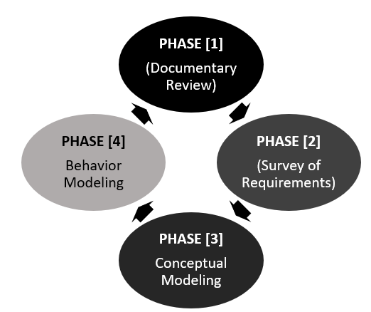
For the development of this research, the following phases we can see in fig. 1:
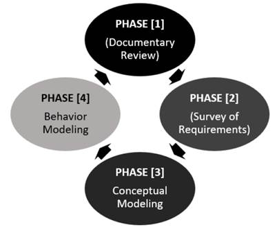
Figure 1: Phases of the research proposed for the development of the project
-
Document review: In this phase, a review of different documents related to the proposed topic was conducted, with the aim of establishing the artifacts or components that represent the most prominent and important functionalities of the technological solution. Two approaches contemplated by the UML were used: static and dynamic views.
-
Survey of requirements: It is carried out in accordance with the information collected to determine and document the functional and non-functional requirements of the technological solution.
-
Conceptual modeling: A general use case diagram is presented, where the main processes of the technological solution and the interactions with users or actors are visualized. Subsequently,sub-use case diagrams of three of the main processes and their respective documentation are made.
-
Behavioral modeling: The diagrams of the behavior part of the technological solution are elaborated. For this specific case, the construction of a component diagram and a deployment diagram is proposed.
Description of the architecture
This section presents the architecture design of the wireless network used in the project, as well as its components and devices. It also identifies the protocols used for communication, as can be seen in Fig. 2. It is a wireless sensor network (WSN), which is made up of a series of devices distributed autonomously in a growing area. The proposed system consists of three sensor nodes, and each of these nodes consists of a Lucy3 programmable card, to which a temperature and humidity sensor and a soil humidity sensor are connected. Each node is located at a distance of 100 linear meters from each other, covering a total area of 300 linear meters of coffee crops. The nodes communicate with each other wirelessly via the ZigBee protocol of the modules (Xbee Module) installed in each one. They also communicate with the Gateway, which is responsible for complementing the information sent wirelessly with a wired network. The protocol selected for the project is the ZigBee standard in an ISM 2.4 GHZ channel, with a transmission speed of 250 Kbps, and based on the IEEE 802.15.4 or IEEE 802.11 (WIFI) standards or proprietary radios, which are normally 900 MHz [6]. The Zigbee protocol was selected for the project considering factors such as low device costs, transmission distance, and low power consumption of nodes and sensors.

Figure 2: Architecture of the wireless sensor network and the cloud platforms
A Gateway is responsible for coordinating and communicating the sensor nodes with the base station through the 802.3 standard. Finally, the data collected through the sensors is sent to a central unit or base, where it is uploaded to the cloud platform, Ubidots, which is a very user-friendly platform for monitoring sensors and actuators, in addition to its ease of configuration and low costs when acquiring a charging plan and data monitoring is desired. This information is sent from the base station for later storage and processing. Subsequently, a file in CSV format is downloaded from this platform. This input is uploaded to the BigML platform, where it goes to the information analysis phase and the application of the supervised learning model, which allows decision-making regarding the behavior of the environmental variables in the crop and their corresponding corrective measures or actions to be taken.
For the communication between sensor nodes and Gateway, we found several standards that meet the necessary characteristics and conditions, but the ZigBee 802.15.4 protocol or standard was selected, mostly due to economic factors. The ZigBee Alliance [7], comprises an association of industries that work together to develop standards and products. ZigBee is the name of the specification for a set of high-level wireless communication protocols for use in low-consumption digital broadcasting applications, which is based on the IEEE 802.15.4 standard for wireless personal area networks Network or WPAN. ZigBee technology is integrated into a wide range of products and applications for commercial, industrial, and government consumers.
System requirements
Requirements engineering allows us to know the needs of the interested parties with respect to an information system, regardless of whether it is based on hardware components for operability or functionality. In the same way, it is evident that hardware without software does not make any sense.
It is interesting to know the opinion of some experts on the term requirements. According to [8], it refers to a condition or need of the user to solve a problem and achieve a goal. Another definition given by [9] states that requirements are the capabilities and conditions with which the proposed system must be identified. Likewise, [9] define it as the branch of software engineering that deals with setting the objectives, functions, and restrictions of software systems, as well as with the relationship between these factors in order to establish precise specifications. According to [10], requirements engineering is the discipline in charge of developing complete, consistent,and unambiguous specifications, which will serve as the basis for common agreements between all parties involved, where the functions that the system will perform are also described. In general, we can say that it is a process by which different points of view are exchanged between users, clients,sponsors (i.e., stakeholders), and members of a development team, in order to collect and model what and how the proposed system should perform. Likewise, this process uses a set of methods,tools, and actors that generate a model from which a requirements document is created.
As for the technological solution to be developed, Table I shows its functional requirements, which, according to [11], are those that express or describe the nature of the system’s operation in relation to its environment, regardless of its implementation. They also specify how the system should react to particular inputs and how it should behave under particular situations. In general they determine what the system should do [12].
Table I: Functional requirements of the technological solution

On the other hand, the non-functional requirements must also be considered, which can be defined as those criteria or aspects of the system that do not have a direct relationship with its functional behavior (how should the system interact based on indirect factors?). These requirements are also regarded as restrictions on the services and functionalities offered by the system. According to [13], non-functional requirements represent general characteristics and restrictions of the application or technological solution that is being developed. Additionally, their definition tends to be difficult,since their conformity or non-conformity could be subject to free interpretation, for which it is advisable to accompany its definition with acceptance criteria that can be measured. Regarding the technological solution to be developed, Table II relates the non-functional requirements.
Table II: Non-functional requirements of the technological solution

Conceptual modeling
According to [14], conceptual modeling represents the initial phase of the development of permanent data design and data storage for a system. In many cases, persistent data are managed by a relational database management system (RDBMS). In this phase or stage of the life cycle, it is a matter of establishing how the system will perform the functionalities that were raised in the requirement.In a few words, it will answer the question: how is the system going to do it? It is important to start with an introduction to the Unified Modeling Language (UML).
According to [15], the UML unifies, above all, the 800ch, Rumbaugh (OMT), and Jacobson methods, but its scope will become much broader. At the moment, UML is in the process of standardization with the Object Management Group. Likewise, the author defines UML as a standard language for building software plans. We can divide it into four basic approaches: to visualize,specify, build, and document the artifacts of a system that involves software. In another definition given by [16], UML is a standard that has been adopted internationally by numerous organizations and companies to create diagrams and documentation related to software development (computer programs). It should be clarified that, at this point, we will not focus specifically on the diagrams and documentation of the use cases. It also seems important to know, from the point of view of various experts on the subject, different definitions of what a use case is.
According to [17], a use case is a technique for capturing potential requirements of a new system or software update. Each use case provides one or more scenarios that indicate how the system should interact with the user or with another system to achieve a specific goal. Normally, in use cases, the use of technical jargon is avoided, preferring instead a language closer to the end user.We intend to make an approach to the reader about the interaction of the different actors of the system with its main processes. To this effect, we propose the presentation of the general diagram of use cases of the proposed technological solution, which can be observed in Fig. 3.
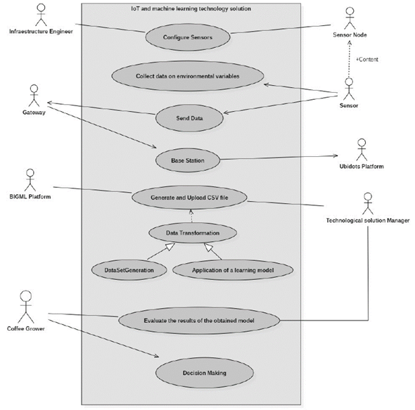
Figure 3: Main use case diagram of the technological solution
At this point, it is important to break down two of the most important processes in the general use case diagram. To begin with, we want to provide a detailed the process of generation and uploading of the CSV file into the BIGML platform, which can be observed in Fig. 4.
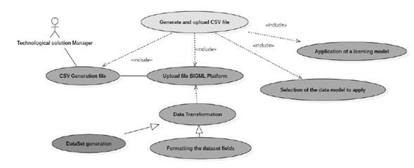
Figure 4: Use case CSV file generation and upload
To continue, it is very important to detail the process carried out to evaluate the results obtained from the model, given that, in this process, it is established whether the model meets the initial expectations for the data analysis and its relevance in the object of study. Fig. 5 shows the use casen in question.

Figure 5: Evaluation of the results obtained from the model
Behavioral modeling
As expressed by [18], behavioral modeling in software development allows determining how certain objects of the system are related and behave. These are not static as in conceptual modeling, but rather have a dynamic behavior. Let us say that I can determine how an object is at a given moment, for example, by sending messages between objects to know its state, which may imply changes in state from one object to another or certain types of activities that a process performs from its beginning to its end. In another definition given by [19], it is emphasized that the objective of dynamic models is to present or describe artifacts that exhibit the behavior of the system over time.
Taking this concept into account, we are interested in knowing which are the components that make up the proposed technological solution at a physical level. For this purpose, we want to present the deployment diagrams, which, as expressed by [20], allow us to represent the hardware structure where our software system will be. To this effect, we can represent each component as nodes. A node is any element that is a hardware resource, that is, it is the generic name for our equipment. Fig. 6 shows the proposed deployment diagram for the technological solution.

Figure 6: Technological solution deployment diagram
Results
We were able to determine the importance of knowing, in an organized and detailed way, the functional and non- functional requirements of a technological solution, since the adequate elaboration and documentation of these requirements depends on subsequent phases of the life cycle that continue to work correctly, in line with the objective of the proposed solution.
Through the general use case diagram, we were able to establish the main processes of the proposed technological solution, as well as each of the related actors in each of these processes. This vision is of utmost importance to determine that the functional requirements of the system are fulfilled in accordance with what is requested by the interested parties of the project. Likewise, the use sub-cases allowed knowing each of the different sub-processes involved in the project, such as the generation and uploading of CSV files, which constitute main input for data analysis on the BIGML platform. Once the data is loaded there, it undergoes a transformation process into the platform’s own formats, and then a learning model is selected and applied. In the other process, the machine learning applied to said data was examined, and it was evaluated whether the obtained results were in accordance with the established parameters.
On the other hand, the deployment diagram allowed us to thoroughly understand the operation of the components, not only of the hardware, but also of the software involved in the proposed technological solution. This is of great importance to understand what happens with the data collected,sent, and processed at a specific moment, and it allows us to have a more detailed view of each component and its interaction in the system.
We were able to appreciate the importance of a modeling language like UML, since it allowed examining the processes and interactions in the system from different perspectives, in addition to identifying the relationships between users and processes.
One of the great advantages of UML is that it can be used and applied in all stages of the life cycle of a technology system, from modeling to validation testing. Another of its great advantages is that it is able to determine the feasibility of a proposal or project in advance, which allows us to financially demonstrate to investors that the idea to be presented brings value to the business.
In this part of the results, we focus more on the obvious advantages of using software engineering through UML modeling than on figures or performance statistics that are not the central object of study. It was possible to show that the application of software engineering through UML modeling allows showing aspects of great importance in the technological solution, such as the different actors involved in the processes through use cases. In the same way, it is possible to obtain vision of the interaction between the different hardware and software components of the solution and understand aspects such as communication between these devices.
Through the conceptual modeling of the technological solution, we were able to identify the most relevant processes that allow us to know what is the basic operation of the solution and the Man-Machine and Machine-machine interactions that are presented.
Equally interesting is that the reader can know, at least in general, the non-functional requirements of the system, which are often more important than the functional requirements themselves. Table II talks about the scalability of the solution that, for now, covers 300 linear meters, but that can be expanded to improve the coverage of the land when deemed necessary. This principle of scalability is very important when considering the development of an IoT solution.
Conclusions
It is important to know the technological aspects of a system, solution, or technological application,but software engineering allows us to delve into more specific details and learn about aspects of great importance in the conceptual and behavioral modeling of a certain software artifact.
Another aspect of great importance is being able to thoroughly understand the functional and nonfunctionalrequirements of a system or technological solution, since, many times, by not considering non-functional requirements, highly relevant quality attributes are neglected or are not given the adequate importance, for example, the response time of a device or server to a request, or access to unauthorized information.
We were able to identify, at a very reduced scale, the importance of the application of software engineering in a technological solution. On the other hand, we established the importance and great applicability of methodologies such as UML in both static and dynamic views of a system.
References
License
Copyright (c) 2022 William Ruiz Martinez, Arnaldo Andrés González Gómez

This work is licensed under a Creative Commons Attribution-NonCommercial-ShareAlike 4.0 International License.
![]()
From the edition of the V23N3 of year 2018 forward, the Creative Commons License "Attribution-Non-Commercial - No Derivative Works " is changed to the following:
Attribution - Non-Commercial - Share the same: this license allows others to distribute, remix, retouch, and create from your work in a non-commercial way, as long as they give you credit and license their new creations under the same conditions.

2.jpg)