DOI:
https://doi.org/10.14483/23448393.19929Published:
2023-05-31Issue:
Vol. 28 No. 2 (2023): May-AugustSection:
Electrical, Electronic and Telecommunications EngineeringComparative Analysis of Boost and Hybrid Boost Converters
Análisis comparativo entre los convertidores Boost y Boost híbrido
Keywords:
Boost converter, Hybrid Boost converter, DC/DC converters, Gain of Voltage and Current, Efficiency (en).Keywords:
convertidor Boost, convertidor Boost híbrido, convertidores DC/DC, ganancia de voltaje y corriente, eficiencia (es).Downloads
References
A. Tazay and Z. Miao, “Control of a Three-Phase Hybrid Converter for a PV Charging Station,” IEEE Trans. Energy Convers., vol. 33, no. 3, pp. 1002–1014, Sep. 2018. [Online]. Available: https://doi.org/10.1109/TEC.2018.2812181 DOI: https://doi.org/10.1109/TEC.2018.2812181
P. K. Maroti, S. Padmanaban, M. S. Bhaskar, M. Meraj, A. Iqbal, and R. Al-Ammari, “High gain three-state switching hybrid boost converter for DC microgrid applications,” IET Power Electronics, vol. 12, no. 14, pp. 3656–3667, 2019. [Online]. Available: https://doi.org/10.1049/iet-pel.2018.6403 DOI: https://doi.org/10.1049/iet-pel.2018.6403
M. Evzelman and S. Ben-Yaakov, “Modeling and analysis of hybrid converters,” in 2012 IEEE Energy Convers. Congr. Expo. (ECCE), 2012, pp. 1592–1598. [Online]. Available: https://doi.org/10.1109/ECCE.2012.6342623 DOI: https://doi.org/10.1109/ECCE.2012.6342623
B. M. Hasaneen and A. A. E. Mohammed, “Design and simulation of DC/DC boost converter,”in 2008 12th Int. Middle-East Power System Conf., Mar. 2008, pp. 335–340. [Online]. Available: https://doi.org/10.1109/MEPCON.2008.4562340 DOI: https://doi.org/10.1109/MEPCON.2008.4562340
B. Axelrod, Y. Berkovich, and A. Ioinovici, “Switched-capacitor/switched-inductor structures for getting trans-formerless hybrid dc–dc pwm converters,” IEEE Trans. Circ. Syst. I Reg. Papers, vol. 55, no. 2, pp. 687–696, 2008. DOI: https://doi.org/10.1109/TCSI.2008.916403
D. F. Cortez, M. C. Maccarini, S. A. Mussa, and I. Barbi, “High static gain single-phase PFC based on a hybrid boost converter,” Int. J. Electronics, vol. 104, no. 5, May 2017. [Online]. Available: https://doi.org/10.1080/00207217.2016.1253782 DOI: https://doi.org/10.1080/00207217.2016.1253782
M. Malik, A. Farooq, A. Ali, and G. Chen, “A DC-DC Boost Converter with Extended Voltage Gain,” in MATEC Web of Conf., vol. 40, Dec. 2015. [Online]. Available: https://doi.org/10.1051/matecconf/20164007001 DOI: https://doi.org/10.1051/matecconf/20164007001
J. C. Rosas-Caro, J. M. Ramirez, F. Z. Peng, and A. Valderrabano, “A DC–DC multilevel boost converter,” IET Power Electronics, vol. 3, no. 1, pp. 129–137, Jan. 2010. [Online]. Available: https://doi.org/10.1049/iet-pel.2008.0253 DOI: https://doi.org/10.1049/iet-pel.2008.0253
F. H. Dupont, C. Rech, R. Gules, and J. R. Pinheiro, “Reduced-Order Model and Control Approach for the Boost Converter With a Voltage Multiplier Cell,” IEEE Trans. Power Electronics, vol. 28, no. 7, pp. 3395–3404, Jul. 2013. [Online]. Available: https://doi.org/10.1109/TPEL.2012.2224672 DOI: https://doi.org/10.1109/TPEL.2012.2224672
S. Belhimer, M. Haddadi, and A. Mellit, “A novel hybrid boost converter with extended duty cycles range for tracking the maximum PowerPoint in photovoltaic system applications,” Int. J. Hydrogen Energy, vol. 43, no. 14, pp. 6887–6898, Apr. 2018. [Online]. Available: https://doi.org/10.1016/j.ijhydene.2018.02.136 DOI: https://doi.org/10.1016/j.ijhydene.2018.02.136
Y. Zhang, J.-T. Sun, and Y.-F. Wang, “Hybrid Boost Three-Level DC–DC Converter With High Voltage Gain for Photovoltaic Generation Systems,” IEEE Trans. Power Electronics, vol. 28, no. 8, pp. 3659–3664, Aug. 2013. [Online]. Available: https://doi.org/10.1109/TPEL.2012.2229720 DOI: https://doi.org/10.1109/TPEL.2012.2229720
F. Velasco, S. Casanova, and D. Perez, “Dynamics of a Boost Converter with Inclusion of Internal Resistance Controlled with ZAD.” Rev. Ing. Energética, vol. 37, no. 2, pp. 144–154, May 2016.
M. Evzelman and S. Ben-Yaakov, “Simulation of Hybrid Converters by Average Models,” IEEE Trans. Ind. Appl., vol. 50, no. 2, pp. 1106–1113, Mar. 2014. [Online]. Available: https://doi.org/10.1109/TIA.2013.2272286 DOI: https://doi.org/10.1109/TIA.2013.2272286
P. Fritzson, A. Pop, A. Asghar, B. Bachmann, W. Braun, R. Braun, L. Buffoni, F. Casella, R. Castro, A. Danos, R. Franke, M. Gebremedhin, B. Lie, A. Mengist, K. Moudgalya, L. Ochel, A. Palanisamy, W. Schamai, M. Solund, B. Thiele, V. Waurich, and P. Ostlund, “The OpenModelica Integrated Modeling, Simulation, and Optimization Environment,” in Proc. Amer. Modelica Conf. 2018, Feb. 2019, pp. 206–219. [Online]. Available: https://doi.org/10.3384/ecp18154206 DOI: https://doi.org/10.3384/ecp18154206
A. Ganeson, P. Fritzson, O. Rogovchenko, A. Asghar, M. Sj ̈olund, and A. Pfeiffer, “An OpenModelica Python Interface and its use in PySimulator,” in Proc. 9th Int. Modelica Conf., Munich, Sep. 2012, pp. 537–548. [Online]. Available: https://doi.org/10.3384/ecp1207653
How to Cite
APA
ACM
ACS
ABNT
Chicago
Harvard
IEEE
MLA
Turabian
Vancouver
Download Citation
Recibido: 14 de septiembre de 2022; Revisión recibida: 27 de diciembre de 2022; Aceptado: 14 de febrero de 2023
Abstract
Context:
In power electronics applications, it is important to make comparisons between converters to choose the device that best suits a particular application. This paper compares the Boost converter and the hybrid Boost converter. The operating models of both converters under study are developed and explained in detail to allow for a proper comparison and analysis.
Method:
Using the passive sign law, the differential equations that govern the behavior of each converter are determined upon the basis of their switching states. Then, circuit simulations are performed by using the OpenModelica software to analyze the output signals of both converters with the same input parameters.
Results:
Comparisons of voltage and current gains, current and voltage time response, and ripple were obtained. Additionally, the efficiency was analyzed by adding resistive losses in each passive element of both converters.
Conclusions:
For high duties, the hybrid Boost converter has a greater capacity to increase the output voltage than the Boost converter. It was also found that the hybrid Boost converter has a low overshoot and a low ripple in the time response of its output signals. However, this converter is less efficient.
Keywords:
Boost converter, hybrid Boost converter, DC/DC converters, voltage and current gains, efficiency..Resumen
Contexto:
En las aplicaciones de electrónica de potencia, es importante realizar comparaciones entre convertidores para escoger el dispositivo que mejor se adapte a una aplicación en particular. Este artículo compara el convertidor Boost y el convertidor Boost híbrido. Los modelos de operación de ambos convertidores en estudio se desarrollan y explican en detalle para permitir una adecuada comparación y análisis.
Método:
Mediante la ley pasiva de signos, se encuentran las ecuaciones diferenciales que rigen el comportamiento de cada convertidor con base en sus estados de conmutación. Acto seguido, se realizan simulaciones circuitales en el software OpenModelica para analizar las señales de salida de ambos convertidores con los mismos parámetros de entrada.
Resultados:
Se obtuvieron comparaciones de ganancia de voltaje y corriente, respuesta en el tiempo de corriente y voltaje, rizados. Además, se analizó la eficiencia al añadir pérdidas resistivas en cada elemento pasivo de ambos convertidores.
Conclusiones:
Para anchos de pulso altos, el convertidor Boost híbrido tiene una mayor capacidad de elevar el voltaje de la salida que el convertidor Boost. También se encontró que el convertidor Boost híbrido presenta bajos sobrepicos y rizados en la respuesta en el tiempo de sus señales de salida. Sin embargo, este convertidor es menos eficiente.
Palabras clave:
convertidor Boost, convertidor Boost híbrido, convertidores DC/DC, ganancia de voltaje y corriente, eficiencia..Introduction
DC/DC converters have sparked great interest in power electronics research, as they offer multiple applications in the automotive sector, power amplification, battery energy storage systems, consumer electronics, and communication. These converters allow controlling the DC voltage at the output from a DC voltage source, acting as energy transfer bridges between sources and loads. There are different boost converter topologies containing a minimum of two semiconductors (a diode and a transistor) and a minimum of one energy storage element (inductor or capacitor). One of the most widely used DC/DC converters in power electronics applications is the Boost converter, given that it offers considerable output voltage gains and high efficiency. For the interconnection of domestic and industrial power with renewable resources, such as photovoltaic (PV) systems, different variations of this converter have been developed, thus leading to hybrid Boost converters, with advantages such as offering higher output voltage gains and improved output signal ripples 1, 2.
Studying the behavior of conventional Boost and hybrid Boost converters, as well as conducting comparative analyses, is necessary to define the converter that best suits an application, with the aim to obtain a high performance. The main objective of this paper is to compare both converters by means of circuit simulations in the OpenModelica software, as well as to present a detailed explanation of their operating principles 3, 4.
This paper presents a complete explanation of these converters’ modeling, starting from the law of passive signs, when the passive elements of the converter absorb or deliver energy in each switching state. In the literature, it is common to find papers that implement hybrid Boost converter models in different systems without a detailed description of the comprehensive derivation regarding the equations governing the model 5. However, a detailed explanation of the model to be used is of paramount importance for the design of power electronics applications 6-9.
Current research studies have implemented hybrid Boost converter topologies without a precise comparison with conventional Boost converters. Therefore, said comparison is presented in this work to establish the advantages and disadvantages of the Hybrid model 10, 13.
The results were obtained by simulating the circuit that allows analyzing the time response of both converters. The OpenModelica software was employed because of its widespread use in the industry, as it is a free and open-source environment based on Modelica. In addition, OpenModelica allows for the simulation of linear and nonlinear systems 14, 15.
The rest of this paper is structured as follows. Section 2 presents the mathematical modeling of the Boost converter. Section 3 presents the mathematical modeling of the hybrid Boost converter. Section 4 corresponds to the results obtained from the simulation of the converter circuits under study. Finally, Section 5 presents the conclusions and analyses derived from this study.
Boost converter modeling
Fig. 1 illustrates the topology of the conventional Boost converter under study. This device is composed of the following elements: an input DC voltage source V i , an inductor L, a switch Q, a diode D, a capacitor C, and a resistive load R.
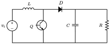
Figure 1: Boost converter topology under study
Methodology for obtaining voltage and current references
The Boost converter features two switching states, which are depicted in Figs. 2 and 3. In the first state, the switch Q is closed, and the diode has reverse polarity, so the inductor L is in parallel to the source Vi and reacts by absorbing energy, while the capacitor C feeds the resistive load R. In the second state, the switch Q is open while the diode D has direct polarity. Now, the inductor L changes its polarity, and, together with the source V i , they deliver energy to the capacitor and the load R.
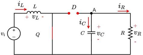
Figure 2: Boost converter with Q closed
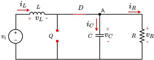
Figure 3: Boost converter with Q open
Differential equations and switched model
To find the equations that govern the converter’s behavior, the differential equations for each switching state are deduced via Kirchhoff’s laws, considering the voltage and current references with respect to node A. Eqs. (1) and (2) refer to when switch Q is closed, while Eqs. (3) and (4) refer to when switch Q is open.


Subsequently, the auxiliary variable u is defined to obtain the switched model. Thus, when u = 1, switch Q is closed; otherwise, when u = 0, switch Q is open. Eqs. (1) and (2) yield Eq. (5) which defines the state of the inductor L as a function of u. On the other hand, Eqs. (3) and (4) yield Eq. (6), which defines the state of the capacitor C as a function of u.


Average model and system gains
To obtain the steady-state mean values of the converter output signals, it is necessary to use the averaging model. This is done by setting the derivatives of Eqs. (5) and (6) as zero. The average of the signals is defined by the average inductor current L (IL), the average capacitor voltage c (Vc), and the average value of the function u (D), which is called the duty cycle.


Eqs. (9) and (10) are obtained by clearing Eqs. (7) and (8), respectively. They refer to the voltage and current gains.


Ripple and continuous condition mode (CCM)
Discretizing Eqs. (1) and (2) while considering ∆t = DfsW results in the inductor current ripple L, Eq. (11), and the capacitor voltage ripple c, Eq. (12).
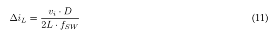

When the converter operates in continuous conduction mode, a reduction in electromagnetic interference and an easy control of the device is guaranteed. This occurs if the average inductor current is greater than the inductor current ripple, as shown in Eq. (13), which has been obtained by substituting Eqs. (10) and (11) into


By making Eq. (13) zero and using the maximum and minimum criterion of differential calculus, the maximum value of K(D) can be found. The maximum value of K(D) is 0, 1481 at a duty of D = 0, 3337. Therefore, if the converter has a Kc greater than this value, it will show CCM for any steady-state duty cycle value.
Modeling the hybrid Boost converter
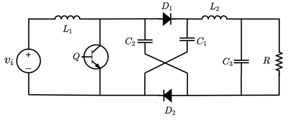
Fig. 4 illustrates the topology of the hybrid Boost converter under study. The converter is composed of the following elements: an input DC voltage source vi , two inductors L1 and L2, a switch Q, two diodes D1 and D2, three capacitors C1, C2 and C3, and a resistive load R.
Methodology for obtaining the voltage and current references
The first switching state of the hybrid Boost converter is shown in Fig. 5. In this state, switch Q is closed, so the inductor L1 absorbs energy by being in parallel to the source vi . On the other hand, capacitors C1 and C2 deliver energy to elements L3, C3, and R. This behavior does not allow for the conduction of diodes D1 and D2. In the second state, illustrated in Fig. 6, switch Q is open, indicating that inductor L1, together with source vi , will now deliver power to capacitors C1 and C2, so diodes D1 and D2 become directly polarized, and inductor L3 reacts by delivering power to C3 and R.
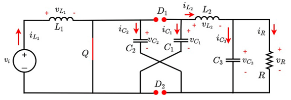
Figure 5: Hybrid Boost converter with Q closed
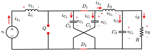
Figure 6: Hybrid Boost converter with Q open
Differential equations and switched model
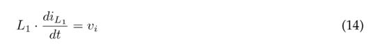
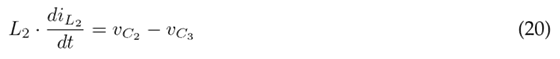
The differential equations that govern the behavior of the converter are found using Kirchhoff’s laws, considering the voltage and current references at node B and assuming C1 = C2 = C. Eqs. (14) to (18) refer to when switch Q is closed, while Eqs. (19) (23) refer to when switch Q is open.


The auxiliary variable u is defined to conveniently write the DEs. When u = 1, Q is closed; otherwise, when u = 0, Q is open. Eqs. (14) and (19) yield Eq. (24), which defines the state of inductor L1; Eqs. (15) and (20) yield Eq. (25), which defines the state of inductor L2; Eqs. (16) and (21) yield Eq. (26), which represents the state of capacitor C1; Eqs. (17) and (22) yield Eq. (27), which refers to the state of capacitor C2; and, finally, Eqs. (18) and (23) yield Eq. (28), which defines the state of capacitor C3.


Average model and system gains
The average of the signals is defined by the average current of the inductors L1 and L2 (iL1 , iL2 ); the average voltage of the capacitors C1, C2, C3 (vC1 , vC2 , vC3 ); and the average value of the function u (D), i.e., the duty cycle.


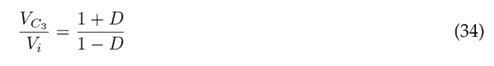
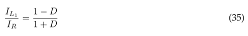
Eq. (34) indicates the voltage gain, which is obtained from Eqs. (29) and (30), while Eq. (35) refers to the current gain, which is obtained from Eqs. (32) and (33).
Ripple and continuous condition mode (CCM)
Discretizing Eqs. (14) and (18) with ∆t = DfsW yields the input current and output voltage ripples given by Eqs. (36) and (37), respectively.


To ensure that the converter operates in continuous conduction mode, the average inductor L1 current must be greater than the inductor L1 current ripple. Eq. (38) is obtained by substituting Eqs. (35) and (36) into


By making Eq. (38) zero and using the maximum and minimum criterion of differential calculus, the maximum value of K(D) can be found. The maximum value of K(D) is 0, 0902 at a duty of D = 0, 2325. Therefore, if the converter has a Kc greater than this value, it will show CCM for any steady-state duty cycle value.
Results
The OpenModelica software (version 1.18) was used to simulate the circuits of both converters. Figs. 7 and 8 show the software implementation of the Boost converter and the Hybrid Boost converter, respectively. These figures show the setpoint block that represents the input voltage of the circuit. Moreover, the pulse block generates a PWM (pulse width modulation) signal that, together with a voltage source, feeds the switch.
Fig. 9 shows the voltage gain vs. the duty of the studied converters. The blue signal represents the voltage gain of the Boost converter, while the red signal illustrates the voltage gain of the hybrid Boost converter. It can be seen that, for both converters, the
 ratio is proportional to the duty. Furthermore, it is evident that the hybrid Boost converter achieves a higher voltage gain from a duty greater than 10 %, and that, from a duty greater than 85 %, the gain of the hybrid Boost converter almost doubles that of the Boost converter.
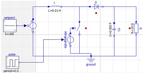
Figure 7: Simulation of the Boost converter in OpenModelica
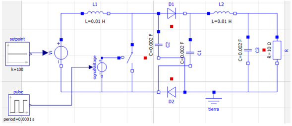
Figure 8: Simulation of the hybrid Boost converter in OpenModelica
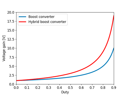
Figure 9: Voltage gain vs. Duty
The current gain of the converters is illustrated in Fig. 10. The blue signal represents the current gain of the Boost converter, while the red signal illustrates the current gain of the hybrid Boost converter. For both converters, the Io/Ii ratio is inversely proportional to the duty. Furthermore, it is observed that the current gain of the hybrid Boost converter decreases faster for duties below 40 % than the current gain of the Boost converter. For duties greater than 40 %, as the duty increases, the current gain signal of the hybrid Boost converter begins to decrease at a faster rate than that of the Boost converter. However, the former will always have a lower current gain.

Figure 10: Current gain vs. Duty
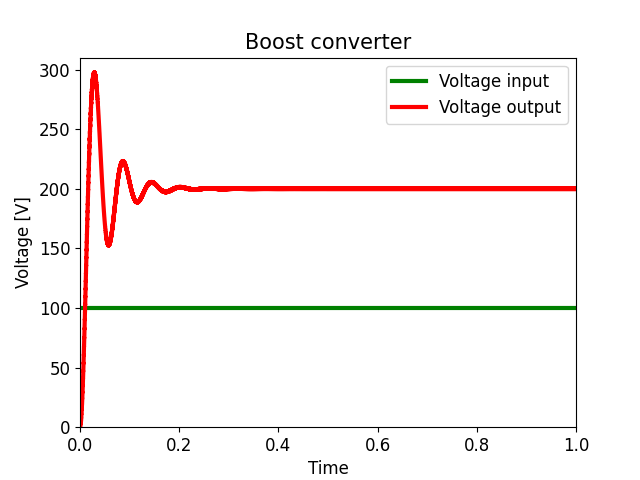
Fig. 11 shows the output voltage (or the voltage across capacitor C or resistor R) and the input voltage V in of the Boost converter. The green and red signals represents the input and output voltage, respectively. It can be seen that, in the transient state, the output voltage has an overshoot of 50 % and a settling time of about 0, 25 seconds. In a steady state, it has a gain of 100 % with respect to the input voltage.
As for the hybrid Boost converter, Fig. 12 illustrates the output voltage (or the voltage across capacitor C3 or resistor R) and the input voltage Vin. The green signal represents the input voltage, and the red signal the output voltage. It is observed that, in the transient state, the output voltage has an over-peak of 45 % and a stabilization time of approximately 0,45 seconds. In addition, in the steady state, it has a gain of 200 % with respect to the input voltage.
Fig. 13 shows the output current (or current in the resistor R) and the input current (or current in the inductor L) of the Boost converter. The green signal represents the input current, and the red signal represents the output current. The input current has an overshoot of 150 % and a settling time of approximately 0, 25 seconds. The output current in the transient state has an overshoot of 50 % and a settling time of approximately 0, 22 seconds. In the steady state, it reports a decrease of 50 % with respect to the input current. Fig. 14 shows the output current (or current at the resistor R) and the input current (or current at L1) of the hybrid Boost converter. The green signal represents the input current, and the red signal represents the output current. It is observed that, in the transient state, the input current presents an over-peak of 122 % and a settling time of approximately 0, 45 seconds. The output current in the transient state has an over-peak of 43 % and a stabilization time of approximately 0, 35 seconds, and it shows a decrease of 33 % in the steady state with respect to the input current.
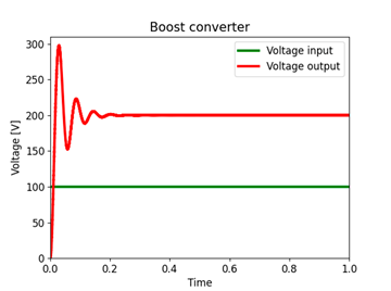
Figure 11: Time response of the voltage in the Boost converter

Figure 12: Time response of the voltage in the hybrid Boost converter
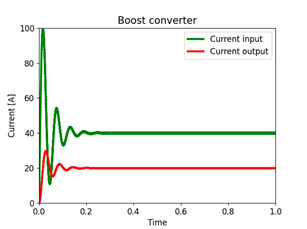
Figure 13: Time response of the current in the Boost converter
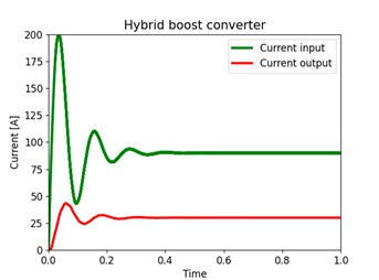
Figure 14: Time response of the current in the hybrid Boost converter
Fig. 15 shows the comparison of the output voltage ripple of the two converters, the red signal refers to the voltage ripple of the Hybrid Boost converter while the orange signal represents the voltage ripple of the Boost converter. The sub-figures in 15 were plotted with the same scale for a proper comparison. The voltage ripple of the Boost converter is 0, 5002 V , while the voltage ripple of the Hybrid converter is 0, 0532 V , resulting in a decrease of 840 %.
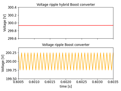
Figure 15: Voltage ripple
Fig. 16 shows a comparison between the output current ripple of the two converters. The red signal refers to the current ripple of the hybrid Boost converter, while the orange signal represents the current ripple of the Boost converter. The sub-figures in Fig. 16 were plotted with the same scale for the sake of comparison. The current ripple of the Boost converter is 0, 050, while the voltage ripple of the Hybrid converter is 0, 005, which constitutes a 900 % decrease.
Fig. 17 shows the efficiency with respect to the duty. This was determined by adding the inductor and capacitor losses of R = 0, 3 in the Open Modelica circuit simulation of both converters. It is observed that, for duties lower than 20 %, the hybrid Boost converter obtains higher efficiency compared to the Boost converter. On the other hand, for duties between 20 and 70 %, the Boost converter manages to a maintain higher efficiency than the hybrid Boost converter. In addition, for duties higher than 70 %, both efficiencies decrease, with a higher efficiency for the Boost converter.
Fig. 18 shows the continuous driving mode for the Boost converter, which is represented by K(D)_B (blue graph), and for the hybrid Boost converter, denoted by K(D)_H (orange graph). This comparison is made to illustrate that the Boost converter has less capacity to enter the discontinuous conduction mode, as the maximum value obtained by the KD_B graph is lower than that of the KD_H graph.
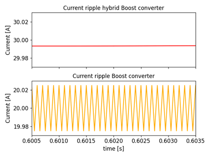
Figure 16: Current ripple
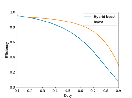
Figure 17: Efficiency
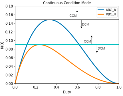
Figure 18: Continuous condition mode
Conclusions
This paper presented a comparative analysis of the Boost and hybrid Boost converters. According to the results obtained, it can be stated that, for high voltages, the hybrid converter has a greater capacity to raise the output voltage than the Boost converter. That is because the former has more capacitors in its hybrid branch, which store energy in each switching state. However, for energy conservation at the output, the hybrid Boost converter has a lower current gain than the Boost converter.
For the same input voltage, the hybrid Boost converter has a lower over-peak and a longer output voltage stabilization time than the Boost converter. On the other hand, both converters exhibit different input currents due to the differences in their topologies. The hybrid Boost converter has a higher input current than the other because it has more elements connected in parallel. It can be said that, to work with hybrid Boost converters, having sources whose rated current is higher than the current required by the converter is advised. As for the output current, the Boost converter exhibits less overshoot and less stabilization time than the hybrid Boost converter.
By analyzing the voltage and current ripple, it is concluded that the hybrid Boost converter has much less ripple than the Boost converter.
By implementing a hybrid Boost converter, there is an 840 % decrease in voltage ripple and a 900 % decrease in current ripple with respect to the Boost converter. By adding resistive losses of 0,3 Ohms in the inductors and capacitors of both converters, the hybrid Boost converter has a higher efficiency than the Boost converter at voltages below 20 %. For voltages above 20 %, the latter is more efficient than the former, as it has fewer elements and therefore less losses
References
License
Copyright (c) 2023 Ana Maria Romero-Carvajal, Nicolas Muñoz-Galeano, Jesus Maria Lopez Lezama

This work is licensed under a Creative Commons Attribution-NonCommercial-ShareAlike 4.0 International License.
![]()
From the edition of the V23N3 of year 2018 forward, the Creative Commons License "Attribution-Non-Commercial - No Derivative Works " is changed to the following:
Attribution - Non-Commercial - Share the same: this license allows others to distribute, remix, retouch, and create from your work in a non-commercial way, as long as they give you credit and license their new creations under the same conditions.

2.jpg)