DOI:
https://doi.org/10.14483/23448393.15741Publicado:
2020-07-09Número:
Vol. 25 Núm. 2 (2020): Mayo - AgostoSección:
Ingeniería Eléctrica y ElectrónicaPower Conversion System for Hybrid Battery-Capacitor Storage
Conversión de Potencia para un Sistema de Almacenamiento Híbrido Batería-Capacitor
Palabras clave:
hybrid electric storage system, battery, capacitor, sliding-mode controller, Boost converter, Buck converter (en).Palabras clave:
sistema de almacenamiento h´ıbrido, bater´ıa, capacitor, controlador por modos deslizantes, convertidor Boost, convertidor Buck (es).Descargas
Referencias
M. Hoel and S. Kverndokk, "Depletion of fossil fuels and the impacts of global warming," Resource and Energy Economics, vol. 18, no. 2, pp. 115-136, jun 1996. https://doi.org/10.1016/0928-7655(96)00005-X
T. Zimmermann, P. Keil, M. Hofmann, M. F. Horsche, S. Pichlmaier, and A. Jossen, "Review of system topologies for hybrid electrical energy storage systems," Journal of Energy Storage, vol. 8, pp. 78-90, nov 2016. https://doi.org/10.1016/j.est.2016.09.006
J. Cao and A. Emadi, "A New Battery/UltraCapacitor Hybrid Energy Storage System for Electric, Hybrid, and Plug-In Hybrid Electric Vehicles," IEEE Transactions on Power Electronics, vol. 27, no. 1, pp. 122-132, jan 2012. https://doi.org/10.1109/TPEL.2011.2151206
H. Zhou, T. Bhattacharya, D. Tran, T. S. T. Siew, and A. M. Khambadkone, "Composite Energy Storage System Involving Battery and Ultracapacitor With Dynamic Energy Management in Microgrid Applications," IEEE Transactions on Power Electronics, vol. 26, no. 3, pp. 923-930, mar 2011. https://doi.org/10.1109/TPEL.2010.2095040
M. Soltani, J. Ronsmans, S. Kakihara, J. Jaguemont, P. Van den Bossche, J. van Mierlo, and N. Omar, "Hybrid Battery/Lithium-Ion Capacitor Energy Storage System for a Pure Electric Bus for an Urban Transportation Application," Applied Sciences, vol. 8, no. 7, p. 1176, jul 2018. https://doi.org/10.3390/app8071176
X. Wang, D. Yu, S. Le Blond, Z. Zhao, and P. Wilson, "A novel controller of a battery-supercapacitor hybrid energy storage system for domestic applications," Energy and Buildings, vol. 141, pp. 167-174, apr 2017. https://doi.org/10.1016/j.enbuild.2017.02.041
K. Jin, M. Yang, X. Ruan, and M. Xu, "Three-Level Bidirectional Converter for Fuel-Cell/Battery Hybrid Power System," IEEE Transactions on Industrial Electronics, vol. 57, no. 6, pp. 1976-1986, jun 2010. https://doi.org/10.1109/TIE.2009.2031197
J. S. Vanegas Varon, M. A. Latorre González, and J. D. Rairán Antoniles, "Cargador manual de baterías: prototipo académico," Revista Ingeniería, vol. 21, no. 1, pp. 83-95, 2016. http://dx.doi.org/10.14483/udistrital.jour.reving.2016.1.a06
"Applications of battery/supercapacitor hybrid energy storage systems for electric vehicles using perturbation observer based robust control," Journal of Power Sources, vol. 448, p. 227444, 2020. https://doi.org/10.1016/j.jpowsour.2019.227444
J. Li, A. M. Gee, M. Zhang, and W. Yuan, "Analysis of battery lifetime extension in a smes-battery hybrid energy storage system using a novel battery lifetime model," Energy, vol. 86, pp. 175 - 185, 2015. https://doi.org/10.1016/j.energy.2015.03.132
G. Ning, B. Haran, and B. N. Popov, "Capacity fade study of lithium-ion batteries cycled at high discharge rates," Journal of Power Sources, vol. 117, no. 1, pp. 160 - 169, 2003. https://doi.org/10.1016/S0378-7753(03)00029-6
E. A. Narváez, C. A. C. Guerrero, and C. L. T. Rodriguez, "Topologies for battery and supercapacitor interconnection in residential microgrids with intermittent generation," Ingeniería, vol. 25, no. 1, pp. 1 - 11, 2020. https://doi.org/10.14483/23448393.15668
R. Han, M. Tucci, A. Martinelli, J. M. Guerrero, and G. Ferrari-Trecate, "Stability analysis of primary plug andplay and secondary leader-based controllers for dc microgrid clusters," IEEE Transactions on Power Systems, vol. 34, no. 3, pp. 1780-1800, 2019. https://doi.org/10.1109/TPWRS.2018.2884876
S. Najafi-Shad, S. M. Barakati, and A. Yazdani, "An effective hybrid wind-photovoltaic system including battery energy storage with reducing control loops and omitting pv converter," Journal of Energy Storage, vol. 27, p. 101088, 2020. https://doi.org/10.1016/j.est.2019.101088
O. Veneri, C. Capasso, and S. Patalano, "Experimental investigation into the effectiveness of a super capacitor based hybrid energy storage system for urban commercial vehicles," Applied Energy, vol. 227, pp. 312 - 323, 2018. https://doi.org/10.1016/j.apenergy.2017.08.086
L. Sun, P.Walker, K. Feng, and N. Zhang, "Multi-objective component sizing for a battery-supercapacitor power supply considering the use of a power converter," Energy, vol. 142, pp. 436 - 446, 2018. https://doi.org/10.1016/j.energy.2017.10.051
M. Sellali, S. Abdeddaim, A. Betka, A. Djerdir, S. Drid, and M. Tiar, "Fuzzy-super twisting control implementation of battery/super capacitor for electric vehicles," ISA Transactions, vol. 95, pp. 243 - 253, 2019. https://doi.org/10.1016/j.isatra.2019.04.029
S. Ahmadi, S. Bathaee, and A. H. Hosseinpour, "Improving fuel economy and performance of a fuel-cell hybrid electric vehicle (fuel-cell, battery, and ultra-capacitor) using optimized energy management strategy," Energy Conversion and Management, vol. 160, pp. 74 - 84, 2018. https://doi.org/10.1016/j.enconman.2018.01.020
A. Etxeberria, I. Vechiu, H. Camblong, and J.-M. Vinassa, "Comparison of sliding mode and pi control of a hybrid energy storage system in a microgrid application," Energy Procedia, vol. 12, pp. 966 - 974, 2011. https://doi.org/10.1016/j.egypro.2011.10.127
B.Wang, J. Xu, D. Xu, and Z. Yan, "Implementation of an estimator-based adaptive sliding mode control strategy for a boost converter based battery/supercapacitor hybrid energy storage system in electric vehicles," Energy Conversion and Management, vol. 151, pp. 562 - 572, 2017. https://doi.org/10.1016/j.enconman.2017.09.007
Z. Song, J. Hou, H. Hofmann, J. Li, and M. Ouyang, "Sliding-mode and lyapunov function-based control for battery/supercapacitor hybrid energy storage system used in electric vehicles," Energy, vol. 122, pp. 601- 612, 2017. https://doi.org/10.1016/j.energy.2017.01.098
D. W. Hart, Electrónica de Potencia, 1st ed. Madrid: Pearson Educación, S.A., 2001. http://www.amperonline.com/sites/library/Electronica%20de%20Potencia.%201ra-Edicion-Daniel-W-Hart.pdf
D. González-Montoya, C. A. Ramos-Paja, and R. Giral, "Improved design of sliding-mode controllers based on the requirements of mppt techniques," IEEE Transactions on Power Electronics, vol. 31, no. 1, pp. 235-247, 2016. https://doi.org/10.1109/TPEL.2015.2397831
H. Sira-Ramirez, "Sliding motions in bilinear switched networks," IEEE Transactions on Circuits and Systems, vol. 34, no. 8, pp. 919-933, aug 1987. https://doi.org/10.1109/TCS.1987.1086242
V. I. Utkin, Sliding Modes in Control and Optimization. Berlin, Heidelberg: Springer Berlin Heidelberg, 1992. https://doi.org/10.1007/978-3-642-84379-2
S. I. S. Garcés, "Contributions to the efficiency and safety of stand-alone dc microgrids," 2018. http://bdigital.unal.edu.co/70614/
Cómo citar
APA
ACM
ACS
ABNT
Chicago
Harvard
IEEE
MLA
Turabian
Vancouver
Descargar cita
Recibido: 17 de diciembre de 2019; Revisión recibida: 6 de abril de 2020; Aceptado: 27 de abril de 2020
Resumen
Context:
Due to the low emissions of CO2 generated by electric systems, those solutions have been receiving attention from industries and academia. However, the electrical storage systems required for a large amount of applications must have high energy and power densities.
Method:
To meet those requirements, this paper proposes an active hybrid energy storage system formed by a battery, i.e. a device with a high energy density, and a capacitor, i.e. a device with a high power capability. The proposed solution also protects the battery by limiting the current derivative.
Results:
Two sliding-mode controllers are designed to regulate both the battery current and the load voltage. The design process guarantees global stability and safe battery operation.
Conclusions:
The controller avoids battery degradation caused by the high-frequency current components since the capacitor assumes those components as demanded by the load profile.
Keywords:
Battery, Boost converter, Buck converter, capacitor, hybrid electric storage system, slidingmode controller..Resumen
Contexto:
Gracias a las bajas emisiones de CO2 de los sistemas eléctricos, estos han ganado mucha atención por parte de la industria y la academia. Sin embargo, los sistemas de almacenamiento de energía requeridos en un sin número de aplicaciones deben garantizar ser de alta densidad de energía y potencia.
Método:
Para satisfacer estos requerimientos, este trabajo propone un controlador no-linear para asegurar la estabilidad de un sistema de almacenamiento de energía híbrido activo, el cual es formado por una batería como dispositivo de alta densidad de energía y un capacitor como el dispositivo de alta densidad de potencia. Asimismo, la solución propuesta protege la batería a través de la limitación de la derivada de la corriente.
Resultados:
Se diseñan dos controladores por modos deslizantes, uno para la corriente de la batería y otro para regular el voltaje en la carga. El proceso de diseño garantiza la estabilidad global del sistema y una operación segura de la batería.
Conclusiones:
El controlador de corriente evita la degradación de la batería causada por los componentes de alta frecuencia de la corriente demandados por la carga. Estos componentes de alta frecuencia son asumidos por el capacitor.
Palabras clave:
Batería, capacitor, controlador por modos deslizantes, convertidor Boost, convertidor Buck, sistema de almacenamiento híbrido..Introduction
Due to global warming, produced in part by fossil fuels [1], the development of alternative electrical systems has increased significantly, e.g. public transportation [2], [3]. One of the main challenges of such development is the power conversion of hybrid energy storage systems (HESS), i.e. systems formed by a battery and a capacitor (or supercapacitor) or a fuel cell. The main objective of a HESS is to reduce the high-frequency current transients reaching the battery to avoid accelerated aging [4] by extracting (or storing) the high-frequency components of the load current in a capacitor, so that the battery provides (or stores) the low-frequency components of the current.
Several research works have been conducted to deal with the power conversion system for HESSs. For example, [3], [4] present multiple topologies for HESSs (passive, semi-active and active); however, the control strategies of each DC/DC converter are not discussed. Another solution is presented in [5], wherein a composite energy storage system (CESS) is designed using an interleaved bidirectional Dual-Active-Birdie (DAB) converter. The control strategy of the DAB converter is based on a proportional current controller for both the battery and the ultracapacitor; hence, no global stability is ensured. In [6], a HESS formed by a battery and lithium-ion capacitor (LiC) is used to protect the battery from the damage caused by high-power rates during the charging and discharging of urban public transportation. However, this HESS has a low-complex current controller for the LiC that is not specified. Similarly, an active HESS for domestic applications is proposed in [7], consisting of a battery and a supercapacitor. Both devices have proportional-integral (PI)-type controllers, one for battery current control and another for the DC-bus voltage control, but the linearisation required for the controller design prevents global stability proof. A similar approach is reported in [8], which proposes the use of a PI-type controller for a three-level bidirectional converter, which together with another unidirectional converter, manages the power of a HESS formed by a battery and a fuel-cell. Another approach is reported in [9], wherein a supercapacitor is used to store the energy generated by a manual mechanical system to charge a battery.
One particular approach for designing and controlling HESSs concerns the connection of power converters in parallel or series structures. For example, [10] presents a HESS for an electric vehicle that is formed by a battery and a capacitor interfaced by bidirectional boost converters. This approach provides a continuous current to the battery due to the series inductor but injects a discontinuous current to the DC bus, thus degrading the power quality (high ripple current components). This solution has two main problems: first, the load of the HESS is modelled using constant impedance, which is not accurate when modelling a DC bus; second, although the DC bus is regulated, no restriction is imposed on the battery current derivative, which could reduce the battery’s lifetime [11], [12]. In addition, the converters are controlled with two sliding-mode controllers (SMCs) to ensure global stability, which is demonstrated independently for each converter. A similar approach is proposed in [13], wherein a capacitor and battery are used to form a HESS. Both devices are interfaced with bidirectional boost converters; hence, a high current ripple reaches the DC bus. The control systems for both converters are cascade structures of PI controllers, so global stability is not ensured. Moreover, no limitation of the battery current derivative is considered. Converters with continuous output currents can be used to provide low harmonic distortion to the DC bus, as in the case of the battery charger proposed in [14]. In that work, which does not present a HESS, a bidirectional buck converter is adopted to interface a generic ESS at the price of high current ripples to the battery, which reduce the battery’s lifetime [11], [12]. The first-level controller of the converter is based on a current controller for a renewable energy source (RES) and a voltage controller for the ESS, but no limitation to the ESS current is provided. The same approach is presented in [15], wherein a bidirectional buck converter is used to interface a battery, avoiding currents with high ripples. However, the converter controller is based on two cascade PI controllers, and without accounting for any limitation of the battery current derivative.
A simpler approach is presented in [16], [17], in which HESSs formed by a capacitor and battery are proposed. However, in those works, only one of the storage devices is interfaced using a DC/DC converter, and, therefore, only one storage device can be controlled. This structure avoids the possibility of decoupling the high-frequency components of the load current from the battery since no limitation into the current derivative is adopted. Moreover, the control systems are, as in the previous cases, cascade structures of PI controllers, which cannot provide global stability. Therefore, other works such as [18], [19] propose parallel structures based on a battery and capacitor interfaced with DC/DC converters, which enable decoupling of the battery dynamics from the DC bus perturbations. However, in [18], both devices are interfaced with boost converters, so high current ripples are injected into the DC bus. Moreover, both converters are controlled using PI structures, but the design of those controllers is not described. Similarly, [19] does not report the converters’ topology, or the controllers’ design. In any case, that work emphasises the use of a capacitor to provide the high-frequency components of the bus current, which is necessary to avoid degradation of the battery’s lifetime. In addition, both works are intended for electric vehicles, for which the speed and lifetime of the storage device is critical.
More advanced control strategies, such as the SMCs, have been used to regulate the parallel structures battery/capacitor used to form HESSs. For example, [20] presents a parallel connection of boost converters to interface a battery and a capacitor with the DC bus, whereby both converters are controlled using PI and SMC controllers. The study shows that the SMC provides better performance and improved stability; however, no limitation to the derivative of the battery current is adopted. Similarly, [21] uses an SMC to control the boost converter interfacing the battery, but there are two problems: no limitation on the current derivative of the battery is considered, and the load is modelled with a constant impedance, which is not an accurate representation of a DC bus. Based on sliding-mode theory, [22] proposes a battery/capacitor HESS based on bidirectional buck converters; hence, a discontinuous current is injected into the DC bus (high current ripple). The SMCs are designed to control the inductor currents, whereby a cascade voltage controller regulates the bus voltage and a cascade power controller ensures the correct power balance. Finally, the controllers’ stability is analysed independently, so the whole system is stable. The main problem with this work is the absence of a limitation on the battery current derivative to avoid accelerated aging due to high-frequency current transients.
Therefore, to provide stable DC bus voltage and protect the battery from high-frequency current transients that could reduce the its lifetime, this paper proposes a power conversion system for HESSs based on bidirectional boost and buck converters. This new power system is designed to provide continuous current to both the battery and the DC bus, and the SMCs are adopted to ensure a fast response and global stability. The rest of the paper is organised as follows: the active topology proposed for the HESS is presented in Section 2, after which the SMC design for each converter, guaranteeing the systems’ global stability, is presented in Section 3. Section 4 reports an application example and the system simulations for a case study. Finally, the conclusions in Section 5 close the paper.
Electrical structure of the power conversion system
The main objective of the proposed solution is to reduce the high-frequency current transients reaching the battery, without affecting the current delivered to the load, by extracting (or storing) the high-frequency components of the load current in a capacitor, so that the battery provides (or stores) the current’s low-frequency components.
Figure 1 presents the circuital scheme of the proposed power conversion system, where voltage source v b represents the battery and C b represents the auxiliary storage capacitor. The battery is isolated from the load by a boost converter, while the capacitor is isolated using a buck converter. The boost converter is used to interface the battery since it imposes a continuous current on the battery, hence avoiding high current transients. Instead, the buck converter is selected to interface the capacitor due to the continuous current provided at the output, which corresponds to an additional voltage regulation capacitor, C dc . This last condition makes it possible to regulate the voltage of C dc to provide a regulated voltage level to the load in any condition: discharge mode (positive battery current), charge mode (negative battery current) and stand-by mode (null battery current).
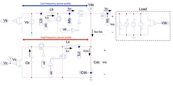
Figure 1: Electrical scheme of the proposed power conversion system for hybrid battery-capacitor storage.
The boost converter has a bidirectional structure (replacing the diode with a MOSFET) with an inductor, Lb, that imposes the battery current (iLb = ib). The buck converter also has a bidirectional structure with an inductor, Lc (iLc current). The voltage of the output capacitor C dc is perturbed by the output current of the boost converter (ibo), the inductor current of the buck converter (iLc), and the load current (idc). Therefore, the iLc current must be controlled to provide a regulated output voltage, v dc , while the battery current, iLb, must be regulated to limit the current derivative within safe limits, which in turn protects the battery from high-frequency currents. It must be pointed out that this solution adopts the same number and type of converters reported in other solutions such as [3] [4] [6], [7], [10], [11], [12], [13], [14], [20], [22] hence no additional costs are introduced due to the power stages. Similarly, the controllers have the same nature that the solutions reported in [20], [21], [22] hence no additional costs are introduced due to the control stages.
The circuital scheme represents the load with current steps, which corresponds to the current profiles with the highest derivative, both positive and negative. Finally, the proposed power conversion system provides regulated voltage to the load in any operation condition, thus behaving as an ideal voltage source.
Sliding-mode controllers (SMCs)
To regulate both the battery current and the load voltage, two SMCs are designed. The first is in charge of regulating the iLb current, imposing a safe profile to the battery current; the second is in charge of regulating the load voltage, vdc. In the following, the mathematical models of the circuit and both SMCs are described:
Mathematical model
The differential equations modelling the inductor currents and capacitor voltages are:


In those equations, ub represents the control signal driving the MOSFETs of the boost converter, while uc represents the signal driving the MOSFETs of the buck converter. Moreover, averaging those equations within the switching period [23] , the average values of the output current in the boost converter, ibo, and its duty cycle, db, are:


SMCs
The objective of this SMC is to regulate the Lb current (iLb) in agreement with a given reference value, ibr. This is achieved with the following switching function Sb and sliding surface Sb = 0:

The derivative of the previous switching function is:

The global stability of the SMC for switched power converters is evaluated using the three conditions described in [24] transversality, reachability and equivalent control. Moreover, in [25] , Sira- Ramirez demonstrated that the reachability and equivalent control conditions are equal, so only one of them must be evaluated. Therefore, any SMC that fulfils both transversality and reachability conditions is globally stable.
Transversality condition
The transversality condition evaluates the presence of the control signal in the derivative of the switching function [26]. Thus, it evaluates the controllability of the system:

Including (8) in (9):

Since (10) is true in any condition, the transversality condition is always fulfilled. Therefore, it is possible to implement an SMC based on the sliding surface Sb = 0.
Reachability condition
The reachability condition analyses the convergence of the switching function, Sb, to the sliding surface Sb = 0 [26]. As such, when Sb is operating under the surface, its derivative must be positive to reach the surface; similarly, when Sb is operating above the surface, its derivative must be negative to reach the surface. The previous conditions are formalised as follows:

The analysis of (11) depends on the sign of the transversality condition (10): since
 0, it means that a positive change in ub produces a negative S
b
derivative, while a negative change in u
b
produces a positive S
b
derivative. Therefore, to achieve
0, it means that a positive change in ub produces a negative S
b
derivative, while a negative change in u
b
produces a positive S
b
derivative. Therefore, to achieve
 must change to 0, while to achieve
 must change to 1. Then, using the value of Sb given in (8) to evaluate the condition given in (11), the following reachability conditions are obtained:


Both inequalities (12) and (13) impose dynamic restrictions on the reference, i br , which is used to define the battery current. The practical dynamic restrictions are given in (14), which must be fulfilled to ensure the operation inside the sliding surface:

Analysing the L b current derivative given in (1), it is concluded that the limits of inequality (14) correspond to the maximum positive and negative derivatives of the L b current; hence, the proposed SMC based on S b enables reaching the fastest response for a boost converter. Finally, since both transversality and reachability conditions are fulfilled, the analyses reported in [25] ensure that the DC/DC converter controlled by the proposed SMC has global stability.
Reference generator
The reference for the battery current ibr must be defined following two conditions:
-
The derivative of i br must fulfil the restrictions given in (12).
-
The average battery power, p b = v b i br , must be equal to the average load power, p dc = v dc i dc . In that way the average power exchanged with the capacitor is zero, hence it has a constant average charge.
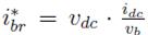
The previous conditions are fulfilled using the structure depicted in Figure 2, which also presents the flowchart of the power balance algorithm. First, the theoretical battery current,
 , needed to balance the capacitor power is calculated as
 , which could exhibit high-frequency components; therefore, a circuit is introduced to limit the derivative of the
 signal. Such a derivative limiter is configured to ensure a maximum current derivative lower than the safe slew-rate value (SR), which depends on the battery specifications. The reference current, i
br
, corresponds to the output of the derivative limiter.
signal. Such a derivative limiter is configured to ensure a maximum current derivative lower than the safe slew-rate value (SR), which depends on the battery specifications. The reference current, i
br
, corresponds to the output of the derivative limiter.
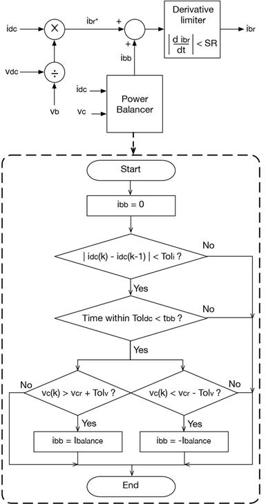
Figure 2: ibr reference generator structure and power balance algorithm.
Second, since high-frequency current transients are not provided in i br , the capacitor charge is not balanced after a high-frequency transient. Therefore, an additional power balance algorithm is used to balance the capacitor charge, which increases or decreases the i br reference using the signal i bb until the capacitor voltage reaches a reference value, v cr , within an acceptable tolerance, Tolv.
This hysteretic tolerance is introduced to avoid voltage chattering around v cr . Moreover, the power balance block is active when the load current is stable within a tolerance band, Tol i , i.e. without high-frequency transients: to activate the power balance block, the changes of the load current, i dc , must be within the tolerance band, Toli, during at least t bb seconds. When those conditions are fulfilled, the signal, i bb , is equal to a safe current magnitude, I balance , used to balance the capacitor as follows: if the capacitor voltage is under the hysteresis band v cr - Tolv, then ibb = Ibalance; instead if the capacitor voltage is over the hysteresis band v cr + Tolv, then ibb = -Ibalance. Otherwise, ibb = 0.
In conclusion, the power balance block only acts when the load current is stable for a predefined time interval.
Controller implementation
The implementation of the SMC based on Sb must be done using a hysteresis comparator to limit the switching frequency [27]. This is achieved by imposing a control law in agreement with the reachability conditions in (12) and (13) but including the hysteresis band (- Hb, +Hb) as given in (15). Therefore, the practical sliding surface becomes - Hb ? Sb ? +Hb, and the controller is stable if the switching function always operates inside the hysteresis band.

The previous control law is implemented using two classical comparators and S-R Flip-Flop. The circuital implementation of such a control law is presented in Figure 3, which also depicts the implementation of the derivative limiter (SR) and the power balance block. The algorithm of that block is coded in C language. Finally, the hysteresis band, Hb, is selected to limit the switching frequency below a practical value.
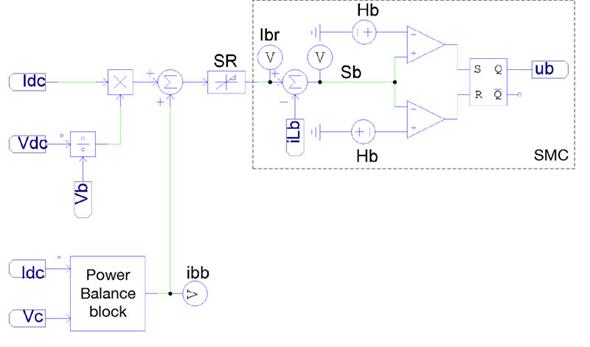
Figure 3: SMC based on Sb.
SMC for the output voltage
The objective of this SMC is to regulate the Lc current (iLc) following a reference value, icr, generated by a voltage controller, which in turn must provide a regulated output voltage, vdc. This SMC is based on the following switching function, Sc, with the sliding surface Sc = 0:

The derivative of the previous switching function is:

Transversality condition
The transversality condition of this part of the system is:
Placing (17) into (18):

Since (19) is always true, the transversality condition is always fulfilled. Therefore, it is possible to implement an SMC based on the sliding surface Sc = 0.

Reachability condition
Considering the transversality value (19) is negative, the reachability condition is similar to that obtained for the previous SMC:


The previous inequalities impose the following dynamic restrictions to the reference icr:

As in the previous SMC, the L c current derivative given in (2) shows that the limits of inequality (22) correspond to the maximum positive and negative derivatives of the L c current; hence, the reachability conditions are always fulfilled. Moreover, such an expression also suggest that the SMC based on Sc enables reaching the fastest response possible for the buck converter.
Finally, as for the previous SMC, since both the transversality and reachability conditions are fulfilled, the analyses reported in [25] ensure that the buck converter controlled by this SMC has global stability.
Equivalent dynamics of the SMC
The action of the SMC based on S c over the buck converter (high-frequency power profile in Figure 1) enables imposing a desired current profile, i cr , in L c . Therefore, L c could be modelled as a controlled current source with value i cr . Moreover, in steady-state conditions, the battery must provide (or store) the load current, so the steady-state value of i cr is zero. The previous conditions imply that a change, δidc, in the load current is equal to the difference between the new load current (after the perturbation) and the steady-state current at the output of the boost converter, I bo . In mathematical terms, the load current after perturbations is given by (23), where I dc is the steadystate current of the load (before the perturbation). Finally, the load current perturbation is calculated in (24) as the difference between the load current and the steady-state current at the output of the boost converter, I bo .


From the circuit depicted in Figure 1 and from Eqs. (3), (5) and (24), the output capacitor current is:

Applying the Laplace transformation to Eq. (25):

The block diagram of the equivalent system is depicted in Figure 4, which includes the reference value, v r , for the load voltage and an additional controller, G v (s), for defining the reference, i cr , of the SMC. This paper proposes implementing G v (s) using a fixed gain, k p , which produces the following closed-loop dynamics:
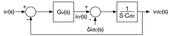
Figure 4: Equivalent system of Sc.

Therefore, kp is designed using (28) to impose a desired settling time, t s, on the load voltage

Equations (27) and (28) indicate the stability of the bus voltage: kp and C
dc
always have positive values; hence, the equivalent closed-loop pole of (27) is located at
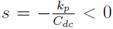 , which ensures the global stability of the bus voltage.
Controller implementation
Similar to the implementation of the previous controller, the SMC based on S c must be implemented using a hysteresis comparator to limit the switching frequency [27]. In this case the control law is in agreement with the reachability conditions in (20) and (21), including the hysteresis band (-H c , +H c ) as given in (29). Therefore, the practical sliding surface becomes -H c ? S c ? +H c ; and the controller is stable if the switching function always operates inside the hysteresis band.

Such a control law is implemented using two classical comparators and S-R Flip-Flop. Figure 5 presents the circuital implementation, wherein the hysteresis band H c is selected to limit the switching frequency below a practical value.
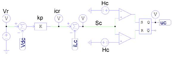
Figure 5: SMC based on Sc.
Design example and circuital simulations
To illustrate the system design and performance, the parameters given in Table I were considered, and the hysteresis bands were selected to limit the switching frequencies up to 200 kH z . Finally, the controller parameter, kp = 1;333, was calculated from (28) to impose a settling time equal to 0,3 ms.
Table I: Simulation parameters
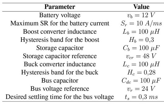
Figure 6 presents the behavior of the power system for fast current transients in the load current: it is observed that both positive and negative currents are imposed by the load, but in all cases the load voltage is successfully regulated. Moreover, the limitation of the slew-rate of the battery current is also observed, which also corresponds to the current of the inductor L b . Therefore, the proposed solution was effective in any operation condition: charging the battery, discharging the battery, and without energy exchange with the battery (stand-by mode). Figure 7 presents different phase planes of the power system for the simulation presented in Figure 6. Figure 7(a) shows the phase plane for the buck converter, which regulated the bus voltage: it was observed that the bus voltage was around the reference value independent of inductor current i LC , which could be positive (discharge), negative (charge) or zero (stand-by). Figure 7(b) shows the switching function, S c , of the buck converter, which always operated in the hysteresis band - Hc ? Sc ? +Hc; hence, the sliding-mode existed, and the system was globally stable. Figure 7(c) presents the phase plane of the boost converter, where the battery current (buck inductor current) followed with null error the current reference in any condition, i.e. discharge (positive), charge (negative) or stand-by (zero). Finally, Figure 7(d) shows the switching function, Sb, of the boost converter, which also operated in the hysteresis band - Hb ? Sb? +Hb; thus, the sliding-mode existed and the closed-loop boost converter was globally stable.
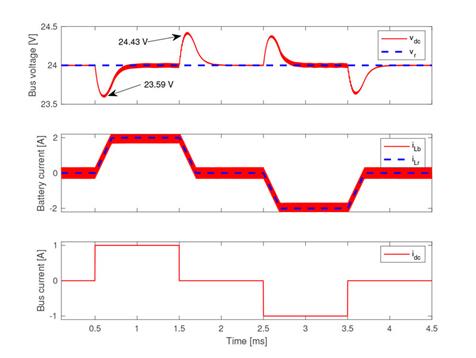
Figure 6: Simulation of the power system under fast load perturbations.
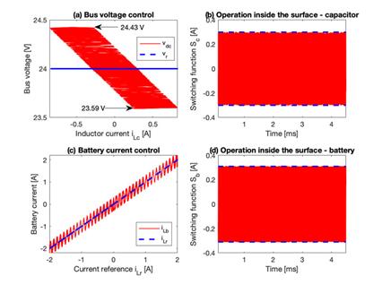
Figure 7: Phase planes of the power system under fast load perturbations.
Figure 8 presents the simulation of two consecutive current transients, which increased the current load and; after the second perturbation, the load current remained constant (equal to 2 A). The simulation showed that both perturbations reduced the Cb capacitor voltage since the capacitor was in charge of delivering the high-frequency components of the transient. In this example, the power balance block was configured to start the compensation after tbb = 2 ms of stable conditions, introducing a compensation current, ibb = 250 mA. However, any other values could have been used depending on the particular application. The simulation (Figure 8) showed that the power balance block increased the inductor current of the boost converter by 250 mA, over the current requested by the load, to charge the capacitor. In fact, when the capacitor voltage was restored to vcr = 48 V , the compensation current, i bb , was set to 0 A.
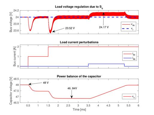
Figure 8: Action of the power balance block.
Figure 9(a) shows the phase plane for the buck converter for this simulation, wherein the bus voltage was regulated around the reference value for any inductor current, iLC , value, e.g. positive (discharge), negative (charge) or zero (stand-by). Figure 9(b) shows the switching function, S c , of the buck converter for this simulation, which also operated in the hysteresis band - H c ? Sc ? +Hc; hence, the sliding-mode existed, and the buck converter was globally stable. Similarly, Figure 9(d) shows the switching function, S b , of the boost converter, which also operated in the hysteresis band - Hb ? Sb ? +Hb, and the boost converter was globally stable. Finally, Figure 9(c) presents the phase plane of the buck converter in terms of the storage capacitor voltage, which was regulated by the power balance block around the reference value for any condition of the inductor current, i.e. discharge (positive), charge (negative) or stand-by (zero).
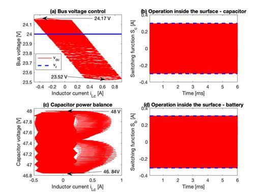
Figure 9: Phase planes of the system under the action of the power balance block.
In conclusion, the simulations presented in this section indicated the correct behavior of the proposed solution:
-
The load voltage was regulated in any operation condition.
-
The battery was not exposed to high-frequency currents.
-
The auxiliary capacitor charge was balanced.
-
Both SMCs exhibited global stability.
Finally, the global stability of the proposed solution significantly improves the reliability and safety of the hybrid power system in comparison with other solutions based on linear controllers, such as the ones reported in [5] , [7] [8] , [13] [16] [17]. Moreover, the limitation of the current slope, provided by proposed solution, also reduced the battery degradation in comparison with solutions where such a limitation is not considered, e.g. [11] , [12] , [13] , [16] , [17] , [20] , [21] , [22] .
Conclusions
This paper reported an active HESS formed by a battery, a capacitor and two DC/DC converters. Two SMCs were designed, one for a boost converter and one for a buck converter. The boost converter interfaced the battery with the load and was controlled to avoid injecting high-frequency transients into the battery. Instead, the second controller operated on the buck converter, which interfaced the capacitor and the load to provide a regulated voltage to the load in any condition. Moreover, the existence of both sliding surfaces was guaranteed, confirming the system’s global stability.
The simulation results demonstrated that both the bus voltage regulation and battery current regulation fulfilled the design criteria. The results also showed that the load voltage was regulated in any operation condition, the battery was not exposed to high-frequency currents, and the auxiliary capacitor charge was balanced.
The main limitation of this solution concerns the use of a lossless energy balance for the regulation of steady-state battery current. This limitation could be addressed in future work by including additional current sensors in the circuit, accounting for parasitic losses, though at the price of increasing the system cost. The experimental verification of this solution is under development, which should account for this limitation. Finally, another future improvement could be the adoption of step up/down high-order converters to enable the connection of any battery to any bus voltage level, e.g. buck-boost converters with input/output filters, Cuk, Sepic or Zeta converters, among others.
Acknowledgements
Acknowledgements
This work was supported by the Instituto Tecnológico Metropolitano (Project P17211), the Universidad Nacional de Colombia and Minciencias (Fondo nacional de financiamiento para ciencia, la tecnología y la innovación Francisco José de Caldas) under the projects “Estrategia de transformación del sector energético Colombiano en el horizonte de 2030 - Energetica 2030”, and “Generación distribuida de energía eléctrica en Colombia a partir de energçia solar y eólica”(Code: 58838, Hermes: 38945).
References
Licencia
Derechos de autor 2021 Sergio Ignacio Serna-Garcés, Carlos Andrés Ramos-Paja, Daniel Gonzalez-Montoya

Esta obra está bajo una licencia internacional Creative Commons Atribución-NoComercial-CompartirIgual 4.0.
![]()
A partir de la edición del V23N3 del año 2018 hacia adelante, se cambia la Licencia Creative Commons “Atribución—No Comercial – Sin Obra Derivada” a la siguiente:
Atribución - No Comercial – Compartir igual: esta licencia permite a otros distribuir, remezclar, retocar, y crear a partir de tu obra de modo no comercial, siempre y cuando te den crédito y licencien sus nuevas creaciones bajo las mismas condiciones.

2.jpg)