DOI:
https://doi.org/10.14483/23448393.15668Published:
2020-03-12Issue:
Vol. 25 No. 1 (2020): January - AprilSection:
Electrical and Electronic EngineeringTopologies for Battery and Supercapacitor Interconnection in Residential Microgrids with Intermittent Generation
Topologías para la Interconexión de Baterías y Supercondensadores en Microrredes de Tipo Residencial con Generación Intermitente
Keywords:
Lithium-ion battery, supercapacitor, DC/DC bidirectional converter, Energy Storage System (ESS), power density, energy density (en).Keywords:
Sistema Híbrido de almacenamiento de energía, batería de ion-litio, supercondensador, Convertidor DC/DC bidireccional, Densidad de potencia, Densidad de Energía (es).Downloads
References
U.G.K. Mulleriyawage, W. Shen, C. Hu, “Battery system selection in DC microgrids for residential applications: An Australian case study”, Proc. 14th IEEE Conf. Ind. Electron. Appl. ICIEA 2019, pp. 1926–1931, 2019. https://doi.org/10.1109/ICIEA.2019.8834035
DOE, “Summary Report: 2012 DOE Microgrid Workshop,” 2012.
C. Wang, L. He, “High-performance Adaptive Control for Inverter-based Residential Microgrids”, 2019 IEEE Energy Convers. Congr. Expo. ECCE 2019, pp. 3516–3523, 2019. https://doi.org/10.1109/ECCE. 2019.8912868
G. Di Somma, M. Caliano, M. Graditi, G. Pinnarelli, A. Menniti, D. Sorrentino, N. Barone, “Designing of CostEffective and Low-Carbon Multi-Energy Nanogrids for Residential Applications”, Inventions, vol. 5, no.7, p. 22, 2020. https://doi.org/10.3390/inven-tions5010007
C. Trujillo et al., Microrredes eléctricas, 1st ed. Bogota: Universidad Distrital Francisco José de Caldas, 2015.
S.Y. Kan, M. Verwaal, H. Broekhuizen, “The Use of Battery-capacitor Combinations in Photovoltaic Powered Products”, J. Power Sources, vol. 162, no.2 SPEC. ISS., pp. 971–974, 2006. https://doi.org/10.1016/j.jpowsour.2005.07.001
M. Chowdhury, “Grid Integration Impacts and Energy Storage Systems for Wind Energy Applications—A Review”, IEEE Power Energy Soc. Gen. Meet., pp. 1–8, 2011. https://doi.org/10.1109/PES.2011.6039798
J.P. Zheng, T.R. Jow, M.S. Ding, “Hybrid Power Sources for Pulsed Current Applications”, IEEE Trans. Aerosp. Electron. Syst., vol. 37, no.1, pp. 298–292, 2001. https://doi.org/10.1109/7.913688
R.A. Dougal, S. Liu, R.E. White, “Power and Life Extension of Battery-Ultracapacitor Hybrids”, IEEE Trans. Components Packag. Technol., vol. 25, no.1, pp. 120–131, 2002. https://doi.org/10.1109/6144.991184
A. Khaligh, “Battery, Ultracapacitor, Fuel Cell, and Hybrid Energy Storage Systems for Electric, Hybrid Electric, Fuel Cell, and Plug-In Hybrid Electric Vehicles: State of the Art”, IEEE Trans. Veh. Technol., vol. 59, no.6, pp. 2806–2814, 2010. https://doi.org/10.1109/TVT.2010.2047877
N. Mendis, K.M. Muttaqi, S. Perera, “Management of Battery-supercapacitor Hybrid Energy Storage and Synchronous Condenser for Isolated Operation of PMSG Based Variable-speed Wind Turbine Generating Systems”, IEEE Trans. Smart Grid, vol. 5, no.2, pp. 944– 953, 2014. https://doi.org/10.1109/TSG.2013.2287874
A. Lahyani, P. Venet, A. Guermazi, A. Troudi, “Battery/Supercapacitors Combination in Uninterruptible Power Supply (UPS)”, IEEE Trans. Power Electron., vol. 28, no.4, pp. 1509–1522, 2013. https://doi.org/10.1109/TPEL.2012.2210736
Y. Zhan, Y. Guo, J. Zhu, L. Li, “Power and Energy Management of Grid / PEMFC / Battery / Supercapacitor Hybrid Power Sources for UPS Applications”, Electr. Power Energy Syst., vol. 67, pp. 598–612, 2015. https://doi.org/10.1016/j.ijepes.2014.12.044
A. Etxeberria, I. Vechiu, H. Camblong, “Hybrid Energy Storage Systems for Renewable Energy Sources Integration in Microgrids : A Review”, Power Electron. Conf. Int., pp. 532–537, 2010. https://doi.org/10.1109/IPECON.2010.5697053
A. Narvaez, C. Cortes, C.L. Trujillo, “Comparative Analysis of Topologies for the Interconnection of Batteries and Supercapacitors in a Hybrid Energy Storage System”, in IEEE 8th International Symposium on Power Electronics for Distributed Generation, 2017. https://doi.org/10.1109/PEDG.2017.7972542
R.K. Singh, N.S. Chauhan, S. Mishra, “A Novel Average Current-mode Controller Based Optimal Battery Charger for Automotive Applications”, in 2012 International Conference on Devices, Circuits and Systems, ICDCS 2012, 2012, pp. 135–139. https://doi.org/10.1109/ICDCSyst.2012.6188690
M. Ortúzar, J. Moreno, J. Dixon, “Ultracapacitor-based Auxiliary Energy System for an Electric Vehicle: Implementation and Evaluation”, IEEE Trans. Ind. Electron., vol. 54, no.4, pp. 2147–2156, 2007. https://doi.org/10.1109/TIE.2007.894713
Q. Xu, X. Hu, P. Wang, J. Xiao, P. Tu, C. Wen, “A Decentralized Dynamic Power Sharing Strategy for Hybrid Energy Storage System in Autonomous DC Microgrid”, Ind. Electron. IEEE Trans., vol. 64, no.7, pp. 5930–5941, 2017. https://doi.org/10.1109/TIE.2016.2608880
Q. Xu, J. Xiao, X. Hu, “Decentralized Power Management Strategy for Hybrid Energy Storage System with Autonomous Bus Voltage Restoration and State of Charge Recovery”, Ind. Electron. IEEE Trans., vol. 0046, no.c, 2017. https://doi.org/10.1109/TIE.2017.2686303
T. Bocklisch, “Hybrid Energy Storage Systems for Renewable Energy Applications,” Energy Procedia, vol. 73, pp. 103–111, 2015. https://doi.org/10.1016/j.egypro.2015.07.582
J. M. Guerrero, M. Chandorkar, T. Lee, P. C. Loh, “Advanced Control Architectures for Intelligent Microgrids; Part I: Decentralized and Hierarchical Control”, Ind. Electron. IEEE Trans., vol. 60, no.4, pp. 1254–1262, 2013. https://doi.org/10.1109/TIE.2012.2194969
A. Narvaez, C. Cortes, C. Trujillo, “Real-Time Frequency-Decoupling Control for a Hybrid Energy Storage System in an Active Parallel Topology Connected to a Residential Microgrid with Intermittent Generation”, in Applied Computer Sciences in Engineering, 2018, pp. 596–605. https://doi.org/10.1007/978-3-030-00350-0_49
A. Kuperman, I. Aharon, “Battery-ultracapacitor Hybrids for Pulsed Current Loads: A Review”, Renew. Sustain. Energy Rev., vol. 15, no.2, pp. 981–992, 2011. https://doi.org/10.1016/j.rser.2010.11.010
How to Cite
APA
ACM
ACS
ABNT
Chicago
Harvard
IEEE
MLA
Turabian
Vancouver
Download Citation
Recibido: 5 de diciembre de 2019; Revisión recibida: 27 de enero de 2020; Aceptado: 13 de febrero de 2020
Abstract
Context:
This paper presents a comparative study of the performance of three topologies for interconnecting Lithium ion batteries and supercapacitors in a hybrid energy storage system for use in electric residential microgrids with intermittent generation. The hybrid system’s main purpose is to prolong battery life, using the supercapacitor to handle the dynamic component of current from a pulsed current load. This work builds upon a preliminary simulation-based study, in which two semi-active topologies were compared and evaluated. Here, we add an active topology to the study and describe the operational benefits of each topology.
Method:
For every topology in this study, a non-isolated half-bridge bidirectional DC converter was used, and a proportional-integral (PI) double-loop linear ACC control algorithm was designed for controlling the converters. In the active topology an additional optimisation-based real-time frequencydecoupling control strategy was employed.
Results:
A parallel active topology allows better management of stored energy in the SC by supporting variation of SC terminal voltages with a DC converter as interface to the DC bus.
Conclusions:
Semi-active topologies are easier to design and control, but the operational benefits of supercapacitors require voltage variation at the terminals. This variation is made possible with an active topology.
Keywords:
Lithium-ion battery, supercapacitor, DC/DC bidirectional converter, Energy Storage System (ESS), power density, energy density.Resumen
Contexto:
Este artículo presenta un estudio mediante simulación del comportamiento de tres topologías para la interconexión de baterías y supercondensadores en un sistema híbrido de almacenamiento de energía con potencial aplicación a microrredes eléctricas residenciales. El estudio se basa en una comparación preliminar de dos topologías semi-activas hecha por los autores. En este artículo se añade una topología activa al estudio comparativo.
Método:
En cada una de las topologías del presente estudio se ha usado un convertidor DC bidireccional de medio puente y como estrategia de control básica se usó un control de corriente promedio de doble lazo. Para la topología activa se utilizó una estrategia de control adicional para el desacople de las componentes dinámicas y promedio de la carga o generación pulsante.
Resultados:
La topología activa permite utilizar mejor la energía almacenada en el condensador, gracias a la posibilidad de variar la tensión en sus terminales.
Conclusiones:
El diseño y control de las topologías semi-activas resulta mucho más sencillo que el de la topología activa en paralelo. No obstante, para aprovechar la capacidad de almacenamiento del supercondensador, la tensión entre sus terminales debe tener una variación importante, lo que se puede conseguir con la topología activa.
Palabras clave:
Sistema Híbrido de almacenamiento de energía, batería de ion-litio, supercondensador, Convertidor DC/DC bidireccional, Densidad de potencia, Densidad de Energía..Introduction
The evolution of electric systems has led to development of electric microgrids, defined as a collection of distributed generators and loads placed within a demarcated border. A microgrid can operate in either grid-connected or islanded mode [1], [2]. At a lower power scale, some authors have introduced the concept of residential microgrids or nanogrids, conceived as microgrids connected at a single point of common coupling, located in a low voltage distribution grid. A residential microgrid can come up by limiting its electric boundary to a single house with a capacity range of 2 - 20 kW[1], [3], [4].
Use of wind turbines or solar panels in residential applications facilitates the application of energy storage systems (ESS) to solve the problems associated with intermittent power generation. Battery ESS are commonly used in such application [5]. However, it has been demonstrated that storing intermittent energy from renewable sources could reduce battery lifetime [6]. In order to solve this problem, combinations of different storage technologies have been studied.
A hybrid energy storage system (HESS) uses two or more energy storage technologies. HESS usage provides a convenient means of using every operational attribute of multiple storage technologies [7]. However, the feasibility of an HESS implementation depends on several technical and economic factors.
Since the late 1990s, one of the most widely used and studied HESS configurations has been the combination of batteries and supercapacitors (SC) [8], [9]. While the main focus has been on electric vehicles[10], other HESS applications have included wind turbines[7], [11], solar generation systems [6] and uninterruptible power supplies (UPS) [12], [13]. Advantages afforded by the combination of batteries and supercapacitors include extension of battery life, rapid energy storage, suitability as an ESS for intermittent energy sources, and reduced environmental impact.
In the specific application of microgrids, HESS design must account for many of the microgrid’s operational factors, including the type of energy supply, the microgrid’s operating mode (interconnected or islanded), the voltage conversion ratio, energy and power ratings, and the chosen power electronics topology[5].
Various topologies exist for interconnection of batteries and supercapacitors in a HESS. These can be classified as passive, active and semi-active. In an active topology the storage elements are connected via DC converters while in a passive topology the storage technologies are directly interconnected[14]. In a semi-active topology, only one of the storage devices is connected through a DC converter, or a single converter is used to connect the pre-connected storage mediums to the load.
This paper presents a study of the performance of three topologies for battery and supercapacitor interconnection in a HESS. The work is based on our own preliminary study of topologies, in which we evaluated two semiactive topologies[15]. Here, the study is extended to include an active topology, and the operational benefits of each topology are described. The paper is nised as follows: A detailed system description and the transfer functions of the system and controllers are described in section 2; section 3 presents the simulation results; our conclusions are presented in section 4.
System description
This study employed a HESS composed of Li-ion batteries and a SC designed for a 5 kW rated capacity residential microgrid. Three topologies for battery and SC interconnection were simulated: Two semi-active and one active. The storage system had a rated energy of 5 kWh and a rated power of 5 kW. The DC bus had a rated voltage of 360 V.
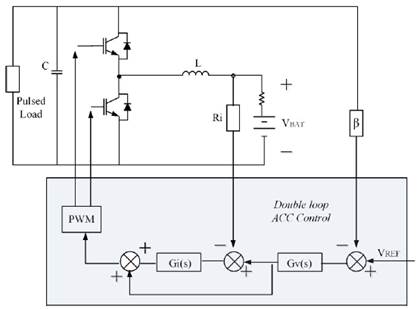
A non-isolated bidirectional half-bridge DC converter topology was chosen for integration of the storage mediums in an active or semi-active topology. Figure 1 shows the topology of the converter and its control architecture with a battery as single storage unit. This converter and its control architecture function as a buck converter when the battery is in charging mode and as boost converter when it is discharging. An ACC double-loop control strategy, commonly used for charging and discharging batteries [16], was selected for this purpose.
Figure 1: Half-Bridge DC/DC converter with an ACC double loop control strategy
To simulate the HESS topologies, a square-shaped load of frequency 10 Hz was connected. The main purpose of combining batteries and supercapacitors within a HESS in this study is extension of battery life by utilising a shortterm storage medium (supercapacitor) to handle the dynamic component of the current load. Some studies have demonstrated that this combination can extend battery life by reducing electric stress in the battery caused by sudden changes in load or generation. These type of systems are economically justified when battery life is ex- tended by 50% or more[17].
MATLAB’s SISOTOOL was the main computational tool used for controller design and calculation of individual elements of the converter. For simulating the entire system, we used Power SIM 11.0.1 software.
We analysed two semi-active topologies and one active topology: The parallel semi-active hybrid topology (Figure 2), the battery semi-active hybrid topology (Figure 3) and the parallel active topology (Figure 4). For the two semi-active topologies, a battery converter was designed and sized for the battery capacity required. For the parallel active hybrid topology, we designed a new converter of appropriate size for the supercapacitor.
Figure 2: Parallel semi-active hybrid topology [23]
Figure 3: Battery semi-active hybrid topology [23].
Figure 4: Parallel active hybrid topology [23]
Table I summarises the elements used in the converters. The main transfer functions of the system under study and the controllers used are shown in Table II.
Table I: DC/DC converter parameters for the battery and supercapacitor
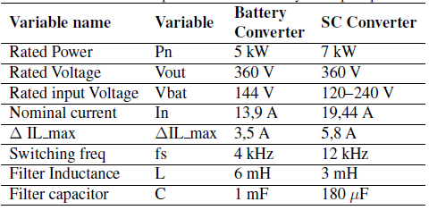
Table II: Basic transfer functions for DC converter control

The variables and transfer functions in Table II were used in the DC converter control loops, as shown in Figure 5. To ensure system stability, the current loop gain T i (s) has a minimum phase margin of 50 degrees with a cut-off frequency much lower than the switching frequency: 10% fs < fc < 5%fs. A similar approach was employed for design of the voltage control loop controller Tv(s), with its cut-off frequency set much lower than the cut-off frequency of the current loop: 10% fs < fcut current < 5%fs. Additionally, for effective separation of average and dynamic load current components, it is recommended that the bandwidth of the battery voltaje control loop be much smaller than the bandwidth of the SC voltage loop. This is to ensure that only the SC compensates for rapid fluctuations and the battery responds to slow dynamic power[18], [19]. Based on the above, with regards to controller design, we consider it convenient to use a higher switching frequency for the SC converter. Table III summarises some of the control parameters.
Figure 5: DC/DC bidirectional converter control loops.
Table III: Control parameters for DC converters.

Simulation results and comparative analysis of the topologies
studied
This section presents simulation results for the three topologies under investigation, obtained using Power SIM 11.0.1 software. The following plots were obtained from the system and topologies described in section 2. First, the DC converter was designed and analysed with li-ion batteries as a single storage medium. The schematic circuit is provided in Figure 1.
As shown in Figure 6(a), the load current fluctuates between 50% and 100% of the nominal current, with a switching frequency of 10 Hz. Figure 6(b) shows the output voltage with a small variation over 360 V due to the implemented double-loop control strategy. Figure 6(c) shows how the battery needs to handle large current variations due to the referred load current. For effective ripple reduction, a 50 _F capacitor was connected between the battery terminals.
Figure 6: Simulation plots of DC converter with batteries as a single storage unit. (a) Current Load (A). (b) Output voltage (V). (c) Battery current (A). (d) Inductor current (A).
Simulation results for the hybrid parallel semi-active topology
We next added a supercapacitor to the previous battery-based storage system, connecting the SC at the battery terminals to create a semi-active hybrid parallel topology, with the expectation that the SC would handle the dynamic component of the pulsed current load. The SC’s time constant was designed to be much longer than the period of the pulsed load, e.g. Tload = 0;2s. This time constant depends strongly on the internal resistances of the battery and SC, so an inaccurate estimation of these electric parameters may result in a poor representation of the behaviour of the real system.
Inclusion of the SC necessitates use of a bigger filter capacitor to reduce over-voltage in the DC bus. After connecting the new filter, the transfer functions and the controllers were updated. Figure 7 shows time plots of the parallel semi-active topology. Figure 7(b) and (c) show how the SC current closely follows the dynamic component of the inductor current with an approximate variation of 16 A. Battery current ripple is thus reduced to less than 2 A, as shown in Figure 7(d). The main advantages of this system behaviour are a potential reduction in battery current capacity, and an increase in battery lifetime resulting from its reduced exposure to electric stress.
Figure 7: Simulation plots for a semi-active parallel topology. (a) Current Load (A). (b) Output volt- age (V). (c) Supercapacitor current (A). (d) Battery current (A).
Simulation results for the hybrid battery semi-active topology
Next, we modified the previous battery-based ESS by connecting a SC to the terminals of the DC bus to obtain a hybrid battery semi-active topology. Simulation results for this topology are shown in Figure 8. The SC was selected using a similar method to that of the previous topology. Thus, as in the previous case, effective power management and reliable predictions of behavior rely strongly on accurate estimation of storage device parameters in the electrical model. The large capacitance connected to the load terminals improves voltage regulation in the DC bus, but has a significant effect on system dynamics and their controllability. Figure 8(b) shows a significant low frequency variation in battery current. As shown in Figure 8(c), the SC acts as a high pass filter on the converter’s high-frequency current component.
Figure 8: Simulation plots for a semi-active battery topology. a) Load current (A) b) Battery current (A). C) Supercapacitor current (A).
Simulation results for the hybrid parallel active topology
HESS energy management in an active topology demands a more complex control strategy [20] because of the need to disaggregate the average and dynamic components of a pulsed current. We therefore selected an optimisation-based real-time frequency-decoupling control strategy for the present study. A real-time control strategy allows the controllers to operate independently without the need for central controllers and communications, improving system reliability[21]. An extended explanation of this control strategy is presented in[18], [19]. In general terms, a virtual low pass filter and high pass filter, related to the parameters R DROOP and C DROOP of Table III, are included in a third control loop for each DC converter, with one converter for every storage technology used. A specific application for residential microgrids with an emulated solar generator is presented in[22].
The complete schematic circuit for the parallel active hybrid topology is shown in Figure 9. The pulsed current load, labelled LOAD in the schematic, is connected to the DC bus. The output voltage remains almost constant over 360 V. The SC converter switching frequency was chosen to be higher than that of the battery converter. The difference in switching frequencies allows for better adjustment of the voltage controllers’ bandwidth and provides the SC converter with faster dynamics. Additionally, the SC converter’s rated power should also be higher because of the current variation in the supercapacitor. SC converter parameters and controller bandwidths for the complete system in a parallel active hybrid topology are summarised in Table I and Table II, respectively.
Figure 9: System Schematic with the implemented control strategy
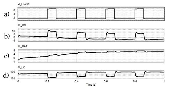
Figure 10 shows simulation plots for the parallel active topology. The injected load current, as shown in Figure 10(a), is divided between the converters in parallel as expected. The load current’s dynamic component is assigned to the SC, and the average component is assigned to the battery. These current components referred to the side of each storage medium are shown in Figure 10(b) and (c). Sudden changes in load current do not result in immediate battery current changes, considerably reducing electrical stress in the battery.
Figure 10: Simulation plots for an active topology HESS. (a) Injected Load Current (A). (b) Battery current plot (A). (c) SC current plot (A) (d) Voltage variations in SC terminals (V).
As mentioned in section 2, using a converter with the SC enables better management of its stored energy. Figure 10(d) shows the voltage in the SC’s terminals. The plot shows a SC voltage variation in the 5V range. SC terminal voltage variation depends on the energy associated with oscillations in the load current as well as the SC value. It is important to note that in the semi-active topologies, SC terminal voltage variation is prevented by direct parallel connection to the terminals of the battery or the DC bus, both of which have defined voltage levels.
Conclusions
We performed a comparison of three HESS topologies composed of lithium-ion batteries and supercapacitors with potential application to residential microgrids. A PI double-loop linear ACC control algorithm and an extended droop control strategy were designed for energy management in the three topologies studied.
In an active parallel topology, effective separation of the dynamic and average components of the injected current depends on the parameters of the virtual filters included in the third control loop of the control strategy implemented.
In an active parallel topology, it is important to have a faster dynamics of the SC converter compared to the battery converter. Selecting larger bandwidths for SC voltage and current controllers normally enables convenient use of a higher switching frequency for the SC converter.
Semi-active topologies are simpler and cheaper than the parallel active topology, but they are less easily con- trolled and have limited operational performance. In contrast, the active topology allows better management of energy stored in the SC because voltages at the terminals can vary. This is made possible by use of a DC converter to connect the SC, allowing a near constant voltage in the DC bus.
A suitable choice of value for the SC depends on two main factors: The energy associated with fluctuations in the injected current, and the used conversion ratio of the DC converter. In addition, by selecting a suitable capacitance value, it is possible to manage the dynamics into the supercapacitor, varying the parameters RDROOP and CDROOP.
Acknowledgements
Acknowledgements
First author thanks Universidad Distrital Francisco José de Caldas for the financial support in his doctoral studies through the study commission contract N 000101-2016.
Referencias
License
From the edition of the V23N3 of year 2018 forward, the Creative Commons License "Attribution-Non-Commercial - No Derivative Works " is changed to the following:
Attribution - Non-Commercial - Share the same: this license allows others to distribute, remix, retouch, and create from your work in a non-commercial way, as long as they give you credit and license their new creations under the same conditions.


![Parallel semi-active hybrid topology [23]](https://revistas.udistrital.edu.co/index.php/reving/article/download/15668/version/11702/16174/92462/2344-8393-inge-25-01-6-gf2.jpg)
![Battery semi-active hybrid topology [23].](https://revistas.udistrital.edu.co/index.php/reving/article/download/15668/version/11702/16174/92463/2344-8393-inge-25-01-6-gf3.png)
![Parallel active hybrid topology [23]](https://revistas.udistrital.edu.co/index.php/reving/article/download/15668/version/11702/16174/92464/2344-8393-inge-25-01-6-gf4.jpg)




2.jpg)
