DOI:
https://doi.org/10.14483/23448393.2845Published:
2008-11-30Issue:
Vol. 8 No. 1 (2003): January - JuneSection:
Science, research, academia and developmentCompresión de Imágenes Craneales Usando Codificación por Transformada Wavelet
Skull image compression using Wavelet Transform coding
Keywords:
Compresión de imágenes, transformada Wavelet, cuantificación, codificación aritmética, algoritmo de mejor base. (es).Downloads
References
JPEG 2000 Part I Final Committee Draft Version 1.0, ISO/ IEC JTC1/SC29 WG1, JPEG 2000.
Mallat, S. (1989, July). A theory for multiresolution signal decomposition: The wavelet representation. IEEE Trans. Pattern Analysis Machine Intelligent. Vol. 11. No 7. pp. 674693.
Wickerhauser Mladen (1994). Adapted Wavelet Analysis from Theory to Software. IEEE Press. pp. 273-276.
Linde Y., Buzo A., y Gray R.M. (1980, January). An Algorithm for Vector Quantizer Design. IEEE Trans on Communications, pp. 84 -95
Antonini M, Barlaud M, Mathieu P, Daubechies I. (1992, April). Image Coding Using Wavelet Transform. IEEE Trans. On Image Processing. Vol. 1. No. 2. pp. 205-220.
Saipetch P, Ho Bruce K.T, Panwar R, Ma Marco, Wei Jun (1995, Sept/Oct). Applying Wavelet Transform with Arithmetic Coding to Radiological Image Compression. IEEE Engineering in Medicine and Biology Magazine. pp. 587-593.
Kjoelen A.,Umbaugh S. y Zuke M. (1998, May/June). Compressing of Skin Tumor Images. IEEE Engineering in Medicine and Biology Magazine. pp. 73 - 80.
Witten IH, Neal RM, and Cleary JG (1987). Arithmetic coding for data compression. Comm. of the ACM, June, pp. 520 - 540.
How to Cite
APA
ACM
ACS
ABNT
Chicago
Harvard
IEEE
MLA
Turabian
Vancouver
Download Citation
Ingeniería, 2003-00-00 vol:8 nro:1 pág:4-9
Skull image compression using Wavelet Transform coding
Compresión de Imágenes Craneales Usando Codificación por Transformada Wavelet
Rodrigo J. Herrera
Miembro Grupo de Investigación en Procesamiento Digital de Señales Universidad Distrital Francisco José de Caldas.
Fernando Ruiz Vera
Asistente de Investigación.
Resumen
Hoy en día la compresión de imágenes es esencial en aplicaciones de transmisión y almacenamiento en bases de datos. Este trabajo expone el diseño de un sistema de compresión haciendo uso de la técnica de codificación por transformación y en particular haciendo uso de la transformada Wavelet. El diseño se centró en un conjunto de imágenes médicas debido a la alta calidad visual que requiere este tipo de imágenes. A causa de la gran variedad de filtros Wavelet disponibles, se escogió un filtro específico de acuerdo con el Algoritmo de Mejor Base. El diseño de la etapa de cuantificación tiene como soporte la modelación estadística de los coeficientes Wavelets, principalmente hacia una distribución Laplaciana. De acuerdo con el algoritmo de Linde-Bruno-Gray, se construye un cuantificador escalar multiresolución general para todo el conjunto de imágenes en estudio. Finalmente, la codificación en entropía se alcanza por medio de un codificador aritmético. Dentro del desarrollo del documento se describen los diferentes análisis hechos para obtener un diseño final con una tasa de compresión igual a 5.43:1 y preservando la calidad de la imagen original.
Palabras clave: Compresión de imágenes, transformada Wavelet, cuantificación, codificación aritmética, algoritmo de mejor base.
Abstract
Now days, image compression is essential in transmission and data base storage applications. This work exposes the design of a compression system using the transform coding technique and in particular using the Wavelet transform. The design is centered on a set of medical images because the high visual quality required for this kind of images. Due to the large diversity of available Wavelet filters, it was chosen a specific filter according to the Best Basis Algorithm. The quantization stage design has as support the statistical modeling of the Wavelet coefficients, mainly towards a Laplacian distribution. Following the Linde-Bruno-Gray algorithm, it is built a general multiresolution scalar quantizer for the whole set of studied images. Finally, the entropy encoding is achieved by means of an arithmetic coder. Inside the document is described the several analysis done to obtain a final design with a compression rate equals to 5.43:1 and preserving the original image quality.
Key words: Image compression, wavelet transform, quantization, arithmetic coding, best basis algorithm.
INTRODUCTION
Because of the high and increasing amount of information managed by communication and information systems today, the research about compression techniques keeps on constantly evolution. Also, current applications require bigger compression rates besides a good quality at the recovered images. From the 90's years, Wavelet transform have become one of the most important tool on the signal processing world. A good example is how Wavelet transform has replaced the Discrete Cosine transform into the JPEG image compression standard [1].
All of the compression systems take advantage of the data redundancy to diminish the amount of storage or bandwidth. Some of them are loseless, i.e., the image before and after compression are exactly equals. However, lossy techniques are more common because their higher compression rates. Transform Coding is a lossy technique constituted by three steps: Transform, Quantization and Entropy Coding. As an important feature, the loss of information occur at the quantization process.
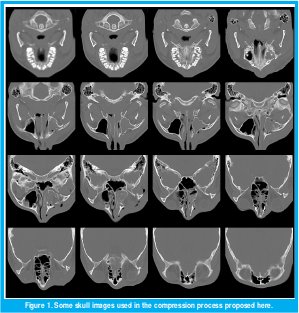
Our study was concentrated over 128 skull images (see Figure 1). As main objective we planed to implement a compression system able to accomplish a good visual quality together with high rate compression. Figure 2 shows the general structure of the designed system.
Section 2 describes the wavelet transform coding scheme used in this paper. First, a review of wavelets in general is presented in addition to the two-dimensional wavelet transform implementation and the best basis algorithm. Next, the quantization stage is explained. We focus particularly on the statistical properties of the wavelet coefficients and the bit assignment. The quantizer design was oriented to find a general codebook for the whole set of images. Various probed alternatives are mentioned. Last, a brief review of the arithmetic coder algorithm explains its operation. Section 3 shows how the quantizer performance was measured. In particular, both the best and the worst case by mean of the MSE are shown. Section 4 summarizes the experimental results obtained after the entropy coding stage.
I. WAVELET TRANSFORM CODING
1.1. WAVELET TRANSFORM
The Wavelet transform can be considered as a Fourier transform evolution, which allows us to represent a signal both at the frequency and time domain. As a result of applying a window function h(t) and its scaled version, defined as
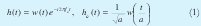
respectively, where a is the scale factor (that is f = f0/α), the simplest way to define the wavelet transform is:

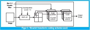
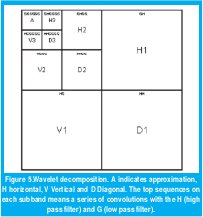
In order to implement the Wavelet transform, it is useful to use a multiresolution analysis [2], which permits computing the wavelet transform as a set of convolutions, with a high-pass filter (h) and a lowpass filter (g), as shown in Figure 3.

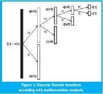
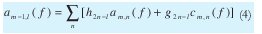
Here n is the resolution level, c contains the detail coefficients (high-pass filtered) and a contains the smoothness coefficients (low-pass filtered). The 2nk sub-index shows the process of sub-sampling by 2. Being the transformation step completely reversible, the wavelet transform does not produce loss of information. Thus, the original signal can be sorted by the inverse transform described in (4).
I. TWO DIMENSIONAL WAVELET TRANSFORM
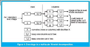
The wavelet transform of a two-dimensional signal, such as an image, can be calculated following the next procedure: First, for each row on the image is calculated one step of decomposition. Second, for each resultant column is calculated one step of decomposition. Third, over the quadrant that contains the smooth values in both vertical and horizontal directions is repeated the whole process. The decomposition is stopped either at the choice level or until reach an image of 2×2 pixels. Figure 4 shows the procedure described above. Our implementation set the decomposition levels to 3, obtaining 10 subbands, as shown in Figure 5.
1.3. CHOOSING A WAVELET FILTER
At the moment of compute the wavelet transform, a large set of different wavelet filters are available. A study over each one of the wavelet filters would have been too extensive. Therefore, the Best Basis Algorithm [3] was used to determine the filter with the greatest concentration of coefficients.
This algorithm establishes that the best basis to represent a signal is the basis whose functional information cost is minimal. Information cost represents the expenses of storing the chosen representation. So, it defines a functional information cost on sequences of real numbers u(k) , to be any real-valued function M satisfying the additive condition below:

Here µ is a real valued function defined on [0,∞) . We suppose that ∑k µ (|u (k)|) converges absolutely; M will be invariant under rearrangements of the sequence u.
Now, for x signal, it is calculated the transform into each basis B as u(k) = B * x(k) = (bk, x). The best basis will be one whose M(u) value is minimal.
Some examples of information cost functions are:
- Number above a threshold. We can set an arbitrary threshold ε and count the elements in the sequence x whose absolute value exceeds ε. This information cost function counts the number of sequence elements needed to transmit the signal to a receiver with precision threshold ε.
- Concentration in lp. Chosen an arbitrary 0<p<2 and set µ (ω) = |ω|p that M (u) = |{u}|pp. Note that if we have two sequences of equal energy ||u|| = ||v|| but M(u) < M(v), then u has more of its energy concentrated into fewer elements.
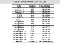
In order to find the optimal representation, it was calculated these two measures setting p=2 and ε=10. As a result, the minimum value was found with biortogonal 4.4 filter. Some of the values obtained for a particular image are shown on the Table 1.
1.4. QUANTIZATION
The purpose of the quantization stage is to restrict the wavelet coefficients to a small set of values and allows a better entropy coding. At the current work, we use the most traditional method, the well-known LBG-Algorithm [4]. In order to create a training set of values, this algorithm needs to establish the probability density function (pdf) followed by the data set. Thus, it is necessary a statistical study over the wavelet coefficients in each one of the ten subbands.
1.5. STATISTICAL PROPERTIES OF WAVELET COEFFICIENTS
Several previous works [5], [6] illustrate how the detailed wavelets coefficients are well approximated by a Laplacian distribution, given by (6). In addition, given that the lowest resolution subband is a low-passed version of the original image, it is expected to find a similar statistical behavior between both of them.

Since Laplacian distribution can be seen as a double exponential distribution, given by (7), the detailed coefficients were modeled as a negative and positive branch with the parameters wrote down on Table 2.
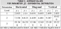
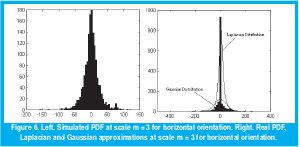
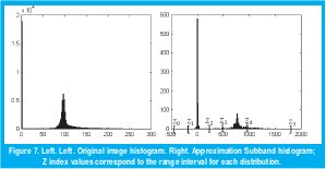
To illustrate how the coefficients are well described by a Laplacian distribution, Figure 6 shows real distribution and Laplacian distribution obtained with values contained in Table 2 for one of the images in study.
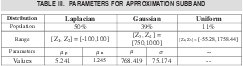
A similar situation occurs when modeling the approximation subband. However, as was explained before, this subband follows a pdf similar to the original image. As a result of studying its histogram, we decide to build a pdf as the composition of Laplacian, Gaussian, and Uniform distributions with parameters included in Table 3 and illustrated in Figure 7.
1.6. BIT ASSIGNMENT
For each one of the 10 subbands, obtained after the transform stage, is assigned a bit rate. To obtain optimal assignment bits involves a complex study, out of focus of the present work; however a good description can be found in [5]. Following a similar research [7], we decide to use the bit rate shown at Table 4 that gives more importance to the high resolution levels and establishes a compression rate equal to 2.6256:1 before coding.
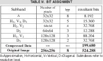
To increase the rate compression reached, they were tested with several options, such as reject the diagonal coefficients of the first resolution level obtaining a bit rate of 3.1411:1, case A. For horizontal and vertical coefficients of the third resolution level were assigned a 4bpp rate instead of 5bpp, increasing the rate compression to 3.1411:1, case B. Likewise, for horizontal and vertical coefficients of the first resolution level were assigned a 2bpp rate instead of 3 bpp, increasing the rate compression to 3.9084:1, case C.
1.7 ARITHMETIC CODING
The coding stage is the last one at the whole compression system. As input, the coder takes an index stream coming from the quantizer and provides variable length codes as output. However, whereas the most common Huffman coder maps each quantization index into a bit stream, the arithmetic coder maps a complete message (a set of indexes) into a bit stream. This property allows coding each index as a fractional number instead of an integer number of bits such as the Huffman coder does. Therefore, the arithmetic coder was chosen over the Huffman coder.
A complete description of arithmetic coding can be found in [8]. The arithmetic coding represents an input message as a real number into the range [0,1) and the code is built with the following algorithm:
- Divide the inter val [0,1) into segments corresponding to the M symbols; the segment of each symbol has a length proportional to its probability.
- Choose the segment of the first symbol in the string message.
- Divide the segment of this symbol again into M new segments with length proportional to the symbols probabilities.
- From these new segments, choose the one corresponding to the next symbol in the message.
- Continue steps (3) and (4) until the whole message is coded.
- Represent the segment's value by a binary fraction.
II. QUANTIZER PERFORMANCE
The images used are sampled as 256x256 black and white images. The intensity of each pixel is coded on 256 gray levels (8 bpp). Numerical evaluation of the coder's performance is achieved by computing the mean square error (MSE) and pixel-to-pixel percentage error between the original image and the coded image.
Following, Figure 8 shows the MSE for different bit assignments (cases A, B, C) over the whole set of images with bit rates of 2.6256, 3.1411and 3.9084 respectively. Even the increasing error, after see the pixel-to-pixel error there is no evidence of a great distortion. Figure 9 shows pixel-to-pixel error of the three cases. Accordingly with the MSE, the worst case is presented on the skull072 image and the best on the skull114.
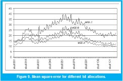
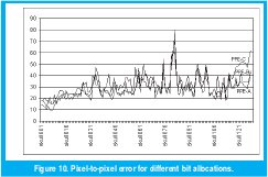
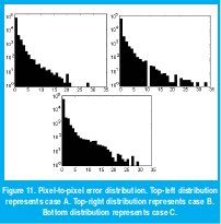
Figure 10 shows the distribution error for the image with the highest MSE (skull072) at three different bit allocations. A logarithmic scale is used on vertical axis and it shows the number of pixels below a percentage error. Clearly, it can be seen how just less than 30 of the 65.536 pixels have an error over 20 % for the case-C (bottom, highest bit rate and MSE). At the top left of this Figure is shown the case-A which has the minor MSE error and only 105 pixels exceed 10% error. At the top right is shown the case-B where just 11 pixels exceed 20% error.
III. EXPERIMENTAL RESULTS
After we probed the quantizer design, the index stream was coded using the arithmetic-coding algorithm explained previously. Due to the fact that there is no loss of information at the coding stage, the final examination consists of obtaining the bit rate and the final compression rate after the entire process. Table 5 summarizes the values of bit rate for each subband and the total number of output bits for the initial design (case A) and the improved design (case C). It is notice that high-resolution levels have a superior bit rate than the low-resolution levels, which validates the importance of high-resolution levels in image information. Another detail to notice is that diagonal subbands present a fewer number of output bits than horizontal and vertical subbands. Therefore, diagonal subbands have lower bit rates. This effect is produced for the wavelet transform, which establishes that horizontal and vertical are the preferential orientations. Given that, the output bits amount depend on the probability of each index coming from the quantizer; a lesser amount of output bits reveal that the quantizer indexes have a higher concentration at these subbands than other orientation subbands.
In the next table is shown how is achieved a 5:43:1 compression rate, which is nearly to say that we have reduced to less than 20% the size of the original image.

IV. CONCLUSIONS
This paper describes an image coding scheme combining the wavelet transform, a scalar quantizer and arithmetic coding.
The biortogonal filter 4.4 was found as the filter with the minimal functional information cost and for that reason it was used in the Wavelet transform stage. The bit assignment chosen permits us to keep a good visual quality besides a reasonable high compression rate. Also, after several attempts, we figure out that high resolution levels coefficients are more important to keep good quality. In addition, resultant data showed how the diagonal coefficients are not so important as horizontal and vertical coefficients.
A good feature of the designed quantizer is the general codebook for the whole set of images. Hence, for transmission applications, it is not needed to send the quantizer information so there is no reduction over the compression rate reached.
Further research should include test on the obtained design over a set of images including both medical and photography sources. Also, a good research would be if it is found an optimal allocation bit in order to achieve higher compression rates.
REFERENCES
[1] JPEG 2000 Part I Final Committee Draft Version 1.0, ISO/ IEC JTC1/SC29 WG1, JPEG 2000.
[2] Mallat, S. (1989, July). A theory for multiresolution signal decomposition: The wavelet representation. IEEE Trans. Pattern Analysis Machine Intelligent. Vol. 11. No 7. pp. 674693.
[3] Wickerhauser Mladen (1994). Adapted Wavelet Analysis from Theory to Software. IEEE Press. pp. 273-276.
[4] Linde Y., Buzo A., y Gray R.M. (1980, January). An Algorithm for Vector Quantizer Design. IEEE Trans on Communications, pp. 84 -95
[5] Antonini M, Barlaud M, Mathieu P, Daubechies I. (1992, April). Image Coding Using Wavelet Transform. IEEE Trans. On Image Processing. Vol. 1. No. 2. pp. 205-220.
[6] Saipetch P, Ho Bruce K.T, Panwar R, Ma Marco, Wei Jun (1995, Sept/Oct). Applying Wavelet Transform with Arithmetic Coding to Radiological Image Compression. IEEE Engineering in Medicine and Biology Magazine. pp. 587-593.
[7] Kjoelen A.,Umbaugh S. y Zuke M. (1998, May/June). Compressing of Skin Tumor Images. IEEE Engineering in Medicine and Biology Magazine. pp. 73 - 80.
[8] Witten IH, Neal RM, and Cleary JG (1987). Arithmetic coding for data compression. Comm. of the ACM, June, pp. 520 - 540.
Rodrigo Javier Herrera García
Ingeniero Electrónico y Magíster en Teleinformática de la Universidad Distrital Francisco José de Caldas. Actualmente se desempeña como profesor de la Facultad de Ingeniería de la Universidad Distrital y director e investigador del Grupo de Investigación en Procesamiento Digital de Señales. rherrera-@udistrital.edu.co
Fernando Ruiz Vera
Estudiante de Ingeniería Electrónica de la Universidad Distrital Francisco José de Caldas. Este artículo es fruto de su Trabajo de Grado para optar al título de Ingeniero Electrónico. Actualmente realiza estudios en Alemania.
Creation date:
License
![]()
From the edition of the V23N3 of year 2018 forward, the Creative Commons License "Attribution-Non-Commercial - No Derivative Works " is changed to the following:
Attribution - Non-Commercial - Share the same: this license allows others to distribute, remix, retouch, and create from your work in a non-commercial way, as long as they give you credit and license their new creations under the same conditions.

2.jpg)