DOI:
https://doi.org/10.14483/23448393.2083Publicado:
2007-11-30Número:
Vol. 13 Núm. 1 (2008): Enero - JunioSección:
Ciencia, investigación, academia y desarrolloA Design Of A Mesoband High Power Electromagnetic Radiator Using A Switched Oscillator And A Corona Current Generator
Palabras clave:
Corona, current generator, mesoband, oscillator, radiator (es).Descargas
Referencias
C. E. Baum, "Switched Oscillators," Circuit and Electromagnetic System Design Note 45, September 2000.
C. E. Baum, "Antennas for the Switched-Oscillator Source," Sensor and Simulation Note 455, March 2001.
D. V. Giri. High-power Electromagnetic Radiators. Harvard University Press, 2004.
F. Román. "A repetitive and constant energy impulse current generator". U.S. patent 5.923.130. July 13th, 1999.
O. Diaz, F. Roman. Improvement of the Output Current Response of an Electrostatic Fast Impulse Current Generator, ICLP2006, Japan.
O. Diaz, F. Roman. A New Fast Impulse Current Generator Based on the Floating Electrodes Properties. ISH 2005, China.
Cómo citar
APA
ACM
ACS
ABNT
Chicago
Harvard
IEEE
MLA
Turabian
Vancouver
Descargar cita
Ingeniería, 2008-00-00 vol:13 nro:1 pág:4-7
A design of a mesoband high power electromagnetic radiator using a switched oscillator and a corona current generator
Felix Vega Stavro
Teacher of electrical and electronic engineering , Universidad Nacional de Colombia. Member of the researching group in electromagnetic compatibility, Universidad Nacional de Colombia. Ph.D. student in electrical engineering, Universidad Nacional de Colombia, guess research at the power systems laboratory, Swiss Federal Institute of Technology of Lausanne (EPFL), Swiss.jfvegas@unal.edu.co
Farhad Rachidi
Titular professor, adscribed to the power systems laboratory, Swiss Federal Institute of Technology of Lausanne (EPFL), Swiss. Manager of the research group in electromagnetic compatibility. farhad.rachidi@epfl.ch
Nestor Peña
Titular Professor, electrical engineering, Universidad de los Andes, Bogota. Research group in telecommunications systems. npena@uniandes.edu.co
Francisco Roman
Titular professor, electrical and electronic engineering, Universidad Nacional de Colombia, member of the researching group in electromagnetic compatibility, Universidad Nacional de Colombia. fjromanc@unal.edu.co
Abstract
This paper presents a design of a mesoband high power electromagnetic radiator using a coaxial switched oscillator and a corona current generator. First, we present an FDTD simulation of the switched oscillator and compared the obtained numerical results to the analytical equation derived by Baum. It is found that the analytical equation is able to reproduce accurately the applied voltage to the antenna. We also describe a coaxial design of a corona current generator that can be used as a source to the switched oscillator. The generator provides a natural DC isolation between the radiating system and the primary source, and is able to produce pulses with amplitudes in the order of a few kA and with rise times of a few nanoseconds.
Key words: Corona, current generator, mesoband, oscillator, radiator.
1. Introduction
The Switched Oscillator (SWO) is a mesoband radiation system proposed by Baum in [1]. It consists of an impulse source connected to a  low-impedance resonant transmission line. The line is connected to an antenna with a high input impedance.

The equivalent circuit of this source is illustrated in Fig.1. The high-voltage source charges the capacitance formed by the line through the impedance  , which is supposed to be higher than both the antenna input impedance
  and the line characteristic and the line characteristic
  . When the switch closes, an impulse voltage
  propagates through the transmission line. When the voltage reaches the antenna, part of it is transmitted to the antenna and part is reflected back, because of the mismatch between the line's characteristic impedance and the antenna´s input impedance. The reflected voltage travels to the switch and it is re-reflected, starting the process again. The voltage is progressively attenuated after each reflection, and tends to decay in an exponential way. The blocking capacitor
  prevents the DC current component to be transmitted to the antenna. It introduces, however, some attenuation in the output voltage that can be avoided by the use of a series inductance (Lc).
For a purely resistive line output impedance, the load voltage can be expressed as:

where:
Equation (1) can be approximated to a damped sinusoid using the procedure proposed in [2]


The Fourier transform of the output signal is therefore given by [4]:

The SWO's central frequency fo can be adjusted by changing the length of the transmission line. The bandwidth and the amplitude of the output voltage can be adjusted by changing the ratio between Z c and Z a.
2. FDTD Simulation of a Coaxial Switched Oscillator
A coaxial SWO has been considered and simulated using a finite-difference time-domain (FDTD) approach. The simulated geometry consists of a coaxial transmission line connected to a non-adapted load. The line is fed by an impulse voltage source represented by a Gaussian waveform with a rise time of 44 ns and a maximum peak of 1 V. The boundary of the geometry is the perfect electric conductor (PEC) body of the outer coaxial sheath. The cell size is 0.16 mm x 0.5 mm x 0.16 mm. The time step is 0.37 ps. The simulation domain contains 61 x 194 x 61 = 72187 cells.
The load impedance and the line characteristic impedance were chosen respectively to be Z a =100 Ohms and Z c =10 Ohms, to have a ratio Z a / Z c = 10. The resulting values for the attenuation constant and central frequency according to equations (3) and (4) are

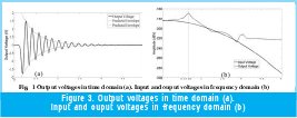
The output voltage is presented in time and frequency domain in Figs. 3a and 3b respectively. It can be seen from Fig. 3(a) that the initial peak of the output voltage is 1.8 V which corresponds to the input voltage peak times (1+). In Fig. 3a, the envelope of equation (2) is also shown, which appears to be in very good agreement with the FDTD simulations.


The resonant behavior of the SWO is shown in Fig. 3(b). It can be seen that the frequency of resonance is about 650 MHz, about 10% lower than the predicted value of 730 MHz given by (6).
Note that the computed RMS output power is 43.75 pW, a value nearly identical to the input power which is 43.76 pW, indicating that all the power delivered to the line is eventually absorbed by the load.
3. Fast impulse current generator: Roman generator
The Roman Generator (RG) is an impulse current generator able to produce pulses with amplitudes in the order of a few kA and with risetimes of a few nanoseconds. The original idea of the Roman Generator [4]-[6] was to reproduce lightning subsequent return strokes current derivatives for Surge Protective Devices (SPDs) testing purposes. During the last decade, different RG prototypes have been designed, constructed and tested. Fig. 4 shows a block diagram of the RG.
The originality of the RG lies on its charging mechanism, which is based on the corona self-charging mechanism of a floating electrode. When a metallic body without protrusions (rounded for example), not connected to the ground, here called floating electrode -FE -, is

immersed in a homogeneous electric static field, a charge division occurs in the FE while its net charge is equal to zero. If the FE has a protrusion (a sharp contour as a needle for example) that distorts the surrounding electric field, a local electric field enhancement could occur around the protrusion. If the corona onset electric field is reached on the protrusion, the FE becomes charged by corona ionic currents [4] and the net charge on the FE will be different from zero. This charging mechanism is called "corona self-charging mechanism".
While the FE is acquiring electrical charge, its electrical potential increases progressively with respect to a grounded electrode. This electrical potential could finally lead to a breakdown between the FE and the grounded electrode (GND). The discharge peak current value is a direct function of the amount of electrical charge stored in the equivalent capacitance between the FE and the GND electrode. The discharge current rise time mainly depends on the inductance and resistance of the spark gap between FE and GND, i.e. the inter-electrode gap distance.
The corona charge mechanism results, for a given high voltage source, in a quasi constant amount of charge transferred to the FE, nearly independent of the generator load. In other words, the RG behaves as a current generator with high internal impedance. Presently, the EMC Group of the National University of Colombia (EMC-UN) is improving the performance of the RG by controlling the gas pressure in the gap, with the goal of producing a 10-kA, 1-ns rise time current impulse.

4. A Mesoband Radiating System Using a Switched Oscillator Coupled to a Roman Generator
The corona charging mechanism described above provides a natural DC isolation between the radiating system and the primary source. One of the main advantages of this device is the low inductance of the discharge path. This novel charging mechanism is a simple alternative to inductor or transformer-based charging systems that require special precautions to prevent arcbreakdown between adjacent loops in the coils.
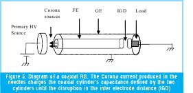
A radiating mesoband system can be conceived based on the concept of SWO and supplied by a RG. A coaxial design of the RG (Fig. 5) can be viewed as a coaxial transmission line charged by the corona sources and discharged in the inter-electrode gap distance. The diameters of the coaxial cylinder can be appropriately determined according to the requirements of characteristic impedance, for instance ten times smaller than the antenna's input impedance. The length of the cylinder should be set to  should be placed in parallel with the load, at the beginning of the transmission line, as shown in Fig. 5. The coaxial cavity should be pressurized in order to increase the breakdown voltage of the structure and the resulting peak voltage.
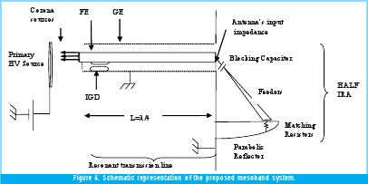
The considered radiating antenna is a half Impulse Radiating Antenna (IRA) [3] which represents a suitable choice because of its unbalanced feeder mechanism.
A typical Half IRA, as described in [4], has an input impedance Z a =100 Ohms. The coaxial transmission line should have a characteristic impedance Z c =10 Ohms. The external and internal diameters of the coaxial line are therefore chosen to be D =50 mm and d =42 mm. The length of the line is 10 cm, corresponding to a resonant frequency of 700 MHz. The resulting capacitance of the line will be C =33 pF. If the line is not pressurized, the breakdown voltage will be about V p =12 kV. The breakdown voltage in the IGD should be therefore set to 6 kV or less, because of the quasi-doubling of the voltage at the line end.

The Voltage in the coaxial capacitance is:

If the constant current produced by the Corona Source is 1 mA, then the capacitance's charging time (T) and the pulse repetition rate (Fr) will be:

According to the simulation performed in Section 2, the maximum peak voltage in the antenna connection point will be about 11 kV.
5. Conclusions
We presented in this paper a design of a mesoband high power electromagnetic radiator using a coaxial switched oscillator and a corona current generator. In the first part of the paper, an FDTD simulation of the switched oscillator was presented and compared with the analytical equation derived by Baum. It is found that the analytical equation is able to reproduce accurately the applied voltage to the antenna.
We also described a coaxial design of a corona current generator that can be used as a source to the switched oscillator. The generator provides a natural DC isolation between the radiating system and the primary source, and is able to produce pulses with amplitudes in the order of a few kA and with risetimes of a few nanoseconds.
References
- C. E. Baum, "Switched Oscillators," Circuit and Electromagnetic System Design Note 45, September 2000.
- C. E. Baum, "Antennas for the Switched-Oscillator Source," Sensor and Simulation Note 455, March 2001.
- D. V. Giri. High-power Electromagnetic Radiators. Harvard University Press, 2004.
- F. Román. "A repetitive and constant energy impulse current generator". U.S. patent 5.923.130. July 13th, 1999.
- O. Diaz, F. Roman. Improvement of the Output Current Response of an Electrostatic Fast Impulse Current Generator, ICLP2006, Japan.
- O. Diaz, F. Roman. A New Fast Impulse Current Generator Based on the Floating Electrodes Properties. ISH 2005, China.
Creation date:
Licencia
A partir de la edición del V23N3 del año 2018 hacia adelante, se cambia la Licencia Creative Commons “Atribución—No Comercial – Sin Obra Derivada” a la siguiente:
Atribución - No Comercial – Compartir igual: esta licencia permite a otros distribuir, remezclar, retocar, y crear a partir de tu obra de modo no comercial, siempre y cuando te den crédito y licencien sus nuevas creaciones bajo las mismas condiciones.


2.jpg)


