DOI:
https://doi.org/10.14483/23448393.23173Published:
2025-10-20Issue:
Vol. 30 No. 2 (2025): May-AugustSection:
Mechanical EngineeringDevelopment of a Safe Feeding Agave Leaf Decortication Machine
Desarrollo de una máquina desfibradora de hojas de agave con alimentación segura
Keywords:
Agave leaves, sisal, sustainability, decorticator, mechanical design, computer assist design (en).Keywords:
Hojas de agave, fique, sostenibilidad, desfibradora, diseño mecánico, sisal, diseño asistido por computadora (es).Downloads
References
D. Tewari, Y. Tripathi, and N. Anjum, "Agave Sislana: A plan with a high chemical diversity and medicinal importance," WJPR, vol. 3, no. 8, pp. 238–249, 2014. https://www.wjpr.net/abstract_show/1538
V. Golfgan, The Aztec and Maya papermakets. New York, NY, USA: JJ Agustin Publisher, 1944.
T. Ahmad, H. Mahmood, Z. Ali, M. Khan, and S. Zia, "Design and development of a portable sisal decorticator," Pak. J. Agric. Sci, vol. 30, no. 3, pp. 209–217, 2017. http://dx.doi.org/10.17582/journal.pjar/2017.30.3.209.217
I. Elfaleh, F. Abbassi, M. Habibi, F. Ahmad, and M. Guerri, "A comprehensive review of natural fibers and their composites: An eco-friendly alternative to conventional materials," Results Eng., vol. 9, pp. 1–31, 2023. https://doi.org/10.1016/j.rineng.2023.101271
S. Palanisamy, K. Vijayananth, T. Mani, M. Palaniappan, and C. Santulli, "The prospects of natural fiber composites: A brief review," Int. J. Lightweight Mater., vol. 7, no. 4, pp. 496–506, 2024. https://doi.org/10.1016/j.ijlmm.2024.01.003
K. Begum and M. Isalm, "Natural fiber as a substitute to synthetic fiber in polymer composites: A review," Res. J. Eng. Sci., vol. 2, no. 4, pp. 46–54, 2013. https://www.isca.me/IJES/Archive/v2/i4/10.ISCA-RJEngS-2013-010.php
D. Solomon, "Application of natural fibers in environmental friendly products," Int. J. Environ. Sci. Nat. Res., vol. 25, no. 4, pp. 147–153, 2020. https://doi.org/10.19080/IJESNR.2020.25.556169
N. Sadeq, Z. Mohammadsalih, and D. Ali, "Natural fibers and their applications: A review," JFES, vol.1, no. 1, pp. 51–63, 2022. https://alfarabiuc.edu.iq/Journal/index.php/Farabi-Eng/article/download/13/6/27
P. Srinivasakumar, M. J. Nandan, C. Udaya, and K. Prahlada, "Sisal and its potential for creating innovative employment opportunities and economic prospects," JMCE, vol. 8, no. 6, pp. 1-08, 2013. https://www.iosrjournals.org/iosr-jmce/papers/vol8-issue6/A0860108.pdf
J. Brenters, “Design and financial assessment of small scale sisal decortication technology in Tanzania”, Master’s thesis, Eindhoven University of Technology, Netherlands, 2000.
M. Kanagu, O. Anotny, and K. Kinguru, “Development of a sisal decorticator for small holder farmers/traders: Redesign, fabrication and field testing”, Bachelor’s thesis, University of Nairobi, Kenya, 2011.
B. Snyder, J. Bussard, J. Dolak, and T. Weiser, "A portable sisal decorticator for kenyan farmers," IJSLE, vol. 1, no. 2, pp. 92–116, 2006. https://doi.org/10.24908/ijsle.v1i2.2087
S. Kunte and A. Amale, "A review paper on structure modification in banana fiber extraction machine," NC-ITSE'16, vol. 7, no. 7, pp. 127-130, 2016. https://ijritcc.org/download/conferences/NCITSE_2016/NCITSE_2016_Track/1468560519_15-07-2016.pdf
J. Villanueva, "Fabrication and testing of abaca fiber decorticator," in Proc. Int. Conf. Technol. Soc. Innov., 2018. http://www.e-jikei.org/Conf/ICTSI2018/proceedings/materials/proc_files/GS_papers/ GS_A003/CameraReadyICTSI2018_GS_A003.pdf
M. Hassan, M. Ali, I. Youssef, and A. Imam, "Development of machine for extracting sisal," Zagazig J. Agric. Res., vol.43, no.3, pp. 2-16, 2016. https://doi.org/10.21608/zjar.2016.101058
I. Vuorinne, J. Heiskanen, M. Maghenda, and L. Mwangala, "Allometric models for estimating leaf biomass of sisal in a semi-arid environment in Kenya," Biomass Bioenergy, vol. 155, no. 1, pp. 1–9, 2021. https://doi.org/10.1016/j.biombioe.2021.106294
R. Naik, R. Dash, D. Behera, and A. Goel, "Studies on physical properties of sisal (Agave sisalana) plant leaves," Int. J. Agr. Sci., vol. 8, no. 48, pp. 2004–2007, 2016. https://bioinfopublication.org/pages/article.php?id=BIA0002964
P. Lanjewar and N. Awate, "Review paper on design and modelling of multipurpose fiber extracting machine," IJESRT, vol. 6, no. 4, pp. 328–335, 2017. https://doi.org/10.5281/zenodo.556240
O. Oyentunji, D. Idowu, and T. Adebayo, "Design and development of a cowpea decorticator," J. Eng. Res. Reports, vol. 25, no. 5, pp. 71–81, 2023. https://doi.org/10.9734/jerr/2023/v25i5912
R. Budynas and N. Keith, Shigley's mechanical engineering design, 9th ed. New York, NY, USA: McGrawHill, 2011.
M. Workesa, “Design, construction and performance evaluation of engine driven WARQE/ENSET (Enset ventricosum) decorticator,” Master’s thesis, Harayama University, Ethiopia, 2018.
MatWeb, "AISI 1020 Steel, annealed at 870 °C (1600°F)," 2024. [Online]. Available: https://www.matweb.com/search/DataSheet.aspx?MatGUID=3e8a4ed96e5f4f16923ec21e95b69585.
F. Beer, E. Russel, J. DeWolf, and D. Mazurek, Mechanic of materials, New York, NY, USA: McGraw Hill, 2018.
SKF Group, “Rolling bearings,” 2018. [Online]. Available: https://www.skf.com/us/products/rolling-bearings
R. Vaishya, A. Misra, A. Vaish, N. Ursino, and R. d’Ambrosi, "Hand grip strength as a proposed new vital sign of health: A narrative review of evidences," J. Health Popul. Nutr., vol. 43, no. 7, pp. 1-14, 2024. https://doi.org/10.1186/s41043-024-00500-y
LISA, "LISA 8.0.0," 2024. [Online]. Available: https://www.lisafea.com/
DEEPSEA, "The ESP32 chip explained: Advantages and applications," 2024. [Online]. Available: https://www.deepseadev.com/en/blog/esp32-chip-explained-and-advantages/#:~:text=The%20ESP32%20is%20a%20versatile,it%2C%20for%20an%20specific%20application.
How to Cite
APA
ACM
ACS
ABNT
Chicago
Harvard
IEEE
MLA
Turabian
Vancouver
Download Citation
Recibido: 20 de enero de 2025; Revisión recibida: 7 de abril de 2025; Aceptado: 9 de mayo de 2025
Abstract
Context:
This work presents the development of an agave decorticator with a safe feeding mechanism. Despite advancements in decortication technology, the literature provides few descriptions that could enable the reproduction of these devices, particularly those with safe feeding mechanisms. Therefore, this article presents the design of an agave decortication machine with a novel feeding system that enhances operational safety. This machine is intended for small-scale production in remote locations with limited access to technology and economic resources, and it is amenable to application in developing countries.
Method:
A mechanical and electronic design methodology was adopted to configure the drum decortication mechanism, the belt drive, the shaft, bearings, the feeding mechanism, and the electronic control and command elements. Structural verification was also carried out through finite element simulations. Theoretical analysis and simulation tools, along with CAD/CAE and electronic design software, were utilized. The construction involved typical workshop machining operations such as turning, drilling, girder cutting, and shield metal arc welding.
Results:
The machine was successfully constructed. Preliminary tests demonstrated a good performance, with a dry fiber production rate of 31.2 kg/h, which is comparable to traditional hand-fed decorticators. The feeding mechanism operates at a significantly low speed (2.5% of the beater drum’s tangential speed), which prevents accidents associated with typical machine configurations. The cost of the equipment is estimated to be 1152 USD, a good value when compared against other similar prototypes in the literature.
Conclusions:
Our agave decorticator with a safe feeding mechanism was successfully designed, built, and preliminarily tested, demonstrating its potential to enhance process safety and efficiency in remote and developing regions while supporting environmental sustainability, sustainable agriculture, and rural employment opportunities.
Keywords:
agave leaves, sisal, sustainability, decorticator, mechanical design, computer- aided design.Resumen
Contexto:
En este trabajo se presenta el desarrollo de una máquina desfibradora de hojas de agave con un mecanismo de alimentación seguro. A pesar de los avances en la tecnología de desfibrado, la literatura ofrece pocas descripciones que permitan la reproducción de estos dispositivos, particularmente de aquellos con mecanismos de alimentación seguros. Por ello, este artículo presenta el diseño de una máquina desfibradora de hojas de agave con un sistema de alimentación novedoso que mejora la seguridad operativa. La máquina está destinada la producción de pequeña escala en ubicaciones remotas con acceso limitado a tecnología, y su aplicación es viable en países en desarrollo.
Método:
Se adoptó una metodología de diseño mecánico y electrónico para configurar el mecanismo de desfibrado con tambor, la transmisión por correa, el eje del tambor, los rodamientos, el mecanismo de alimentación y los elementos de mando y control electrónico. También se realizó una verificación estructural mediante simulaciones por elementos finitos. Se utilizaron herramientas de análisis teórico, simulación y software de diseño CAD/CAE y diseño electrónico. La construcción incluyó operaciones típicas de taller como torneado, taladrado, corte con pulidora y soldadura de arco con electrodo revestido.
Resultados:
La máquina fue construida con éxito. Las pruebas preliminares demostraron un buen desempeño, logrando una producción de fibra seca de 31.2 kg/h, comparable con aquella de las máquinas tradicionales de alimentación manual. El mecanismo de alimentación opera a una velocidad significativamente baja (2.5 % de la velocidad tangencial del tambor de decorticado), lo que previene accidentes relacionados con las configuraciones típicas de estas máquinas. El costo del equipo se estima en 1152 USD, un buen valor si se lo compara con otros prototipos similares en la literatura.
Conclusiones:
Nuestra máquina desfibradora de hojas de agave con mecanismo de alimentación seguro fue diseñada, construida y probada preliminarmente con éxito, demostrando su potencial para mejorar la seguridad y eficiencia del proceso en regiones remotas y en desarrollo, al tiempo que respalda la sostenibilidad ambiental, la agricultura sostenible y las oportunidades de empleo rural.
Palabras clave:
hojas de agave, sisal, sostenibilidad, desfibradora, diseño mecánico, diseño asistido por computadora.Introduction
Sisal, derived from Agave sisalana, a plant native to the hot regions of Mexico, resembles a spiky aloe vera, featuring lengthy, sword-like leaves reaching up to a meter in length 1. These leaves contain lignin and strong cellulose fibers, commonly referred to as sisal, a material utilized since ancient times, notably by civilizations such as the Aztecs and Mayans, who crafted fabric and paper from it 2). To extract the fibers, the soft inner core of the leaves is separated from the fibers 3. Renowned for their durability and resilience against saltwater and wear, sisal fibers are favored for their longevity and with their eco-friendly nature 4,5.
Historically, sisal has found applications in ropes, twines, nets, and coarse fabrics. However, polymericsynthetic fibershavegainedprominenceduetotheircost-effectivenessandmanufacturability 6). Yet, recent environmental concerns surrounding plastics have renewed interest in natural fibers and sustainable materials 4,7,8). With advancements in processing techniques, sisal has now found use in a broader array of products, including carpets, mats, crafts, furniture lining, and even as reinforcement in construction materials 5,9.
Unfortunately, sisal processing techniques have not been industrialized at all, particularly in developing regions. In countries like Colombia, rural areas still rely on rudimentary decorticator machines for sisal processing, which implies safety risks arising from manual leaf feeding, leading to potential hand injuries. To address this issue, we propose a solution that involves the development of an agave decorticator machine with a safe leaf-feeding mechanism. Designed for use in resource-constrained rural settings, this proposal emphasizes simplicity, affordability, and the utilization of locally sourced components.
Mechanical decortication machines have undergone continual refinement, as evidenced by various studies. For instance, 10,11, and 12 introduced decorticators that utilize rotating drums with blunt blades to separate sisal fibers from flesh material. These designs aim to enhance efficiency and safety while minimizing costs through material selection and ease of manufacture.
Similarly, (13 proposed a novel decortication machine for banana pseudostem fiber, incorporating rotating drums with adjustable clearances to improve fiber quality and production rates. 14 presented a specialized abaca fiber decorticator featuring a beater drum mechanism, achieving high fiber recovery rates and quality standards, and 11 focused on smallholder farmers and traders, developing a portable sisal decorticator powered by an internal combustion engine to address electricity limitations. Moreover, 3 and 12 contributed to small-scale sisal processing with portable decorticators, which demonstrated efficient fiber extraction capabilities. These advancements underscore the ongoing efforts to enhance sisal processing technologies, aiming for increased productivity, quality, and safety standards, thereby fostering its commercialization and utilization in sisal-growing regions.
Despite the advancements made regarding decortication technology, and although some of the aforementioned works indicate the use of safe feeding mechanisms 12,15), very few details are provided to enable the reproduction of these machines. Therefore, this article presents the development of an agave decorticator featuring a novel feeding system with improved safety conditions that is intended for small-scale production in remote locations with low access to technology.
Methods
Sisal leaf shape and dimensions
The sisal plant resembles an oversized pineapple, reaching a height of 1.2 to 1.5 m with a short stem 16). Its crescent-shaped leaves, ending in a terminal spine, form a basal rosette surrounding the meristem (Fig. 1a). According to measurements conducted by 17), the leaves exhibit considerable dimensional variability (Fig. 1b). The observed ranges for leaf length, width, and thickness were 0.54-1.62, 0.04-0.12, and 0.01-0.04 m, respectively, with coefficients of variation (COV) of 0.34, 0.27, and 0.40.
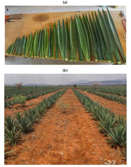
Figure 1: Arrangement of sisal leaves in the plants and their shape 16
Working principles of decortication
In traditional decortication, the beater drum rotates uniformly around a fixed axis of rotation, while the leaf is fed into the drum 3). Assuming that the leaf is fed at a constant speed v, the decortication process can be kinematically modeled while considering the sisal leaf to be stationary and the beater drum to rotate uniformly as it moves horizontally towards the leaf (Fig. 2).
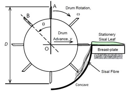
Figure 2: Kinematic model of a decorticator machine 11
11 presented a complete analysis of the kinematic model for the decortication process. Here, the parameter p is calculated as follows:
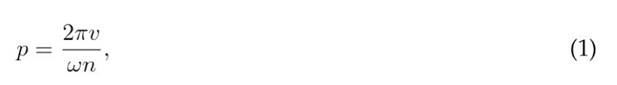
where v is the feeding speed of the leaf relative to the rotating drum, ω is the angular speed of the drum, and n is the number of blades of the drum. The pitch p represents the amount of material from the cortex (leaf tissue) that is scraped each time a drum blade interacts with the leaf. If p were too large, the resulting material removal would be incomplete. On the other hand, if p were too small, then the resulting leaf fiber would be excessively ‘beaten’ by the cylinder blades, unnecessarily expending energy and potentially damaging the fibers 11). Therefore, the appropriate value of p needs to be carefully determined through experimentation. 3 suggest a pitch value of 2.1 mm, which was obtained by conducting experiments involving the decortication of agave leaves while varying several process parameters.
11 deducted an equation for the average power W required to decorticate a leaf in the model presented in Fig. 2. In this study, this equation was adapted to consider mechanical power losses:
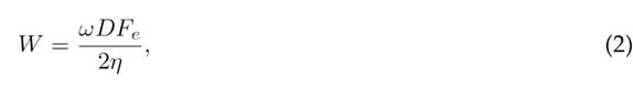
where ω and D are the angular speed and the diameter of the beater drum, and η represents the efficiency of drive system (Fig. 2). F e is the average resistant force of decortication. In their experiments, 3 determined an average force F e of 66 N. To design the decorticator, Eqs. (1) and (2) were adopted in this study.
Design concept
The design concept, presented in Fig. 3, was defined while considering several decorticators from the literature 3), (13), (18), (19). The beater drum is driven by a belt transmission and an electric motor. The feeding mechanism is based on grooved rollers rotating in opposite directions at a lower speed, simulating hand-feeding. The supporting structure is composed of L-shaped plain steel elements. Feeder rollers must be driven by another motor or mechanism, which can be composed of gears or a belt transmission.
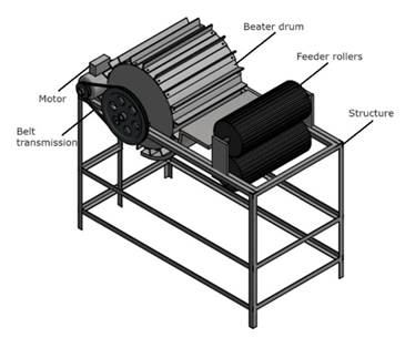
Figure 3: Design concept and main parts
Detailed design
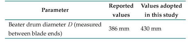
Reference values
To define the operating parameters of the machine, some values reported in the literature were considered, since no measurements of our own were available (column 2 in Table I). The main operating parameters were defined based on the research by 3, who reported the optimal parameters for their experiments on agave leaf decortication. The power reported in Table I is the minimum value reported by 3. In addition, this table summarizes the parameters adopted in this study.
Table I: Operating parameters considered in the design and values adopted in this study
Kinematic and kinetic análisis
Since it was available, an electric motor with a nominal power of 3730 W (5 hp) and an angular speed of 1800 rpm was used in this study. Therefore, the kinematic calculations were adapted for this speed (column 3 in Table I).
As the beater drum speed suggested by 3 is 1250 rpm, we used a belt drive transmission to reduce the motor speed. Two commercial pulleys, measuring 177.8 mm (7 in) and 259 mm (10.2 in) of nominal diameter, were used in the motor and beater drum shaft, respectively, leading to a speed ratio of approximately 1.45. Thus, the actual angular and linear speeds at the blade ends of the beater drum were 1241 rpmand27.5m/s.Theactualpowerrequirement wascalculated based on Eq. (2, considering 16 blades, η = 0,7 —the minimum efficiency of the V belt transmission system reported by 20—, and Fe = 66Nasreported by 3, resulting in a power of 2641.5 W. This is a suitable value for this study; it is lower than that of the available motor.
To calculate the beater drum shaft torque, we considered the previously calculated power requirement of 2641.5 W. Under these conditions, the torque on the beater drum shaft Td was equal to
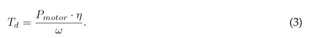
Here, ω is the angular speed of the beater drum, i.e., 136.6 rad/s. By substituting these values into Eq. (3), the torque on the shaft of the drum is obtained: 13.5 N·m.
Beater drum belt transmission calculations
As shown in the free-body diagram of the minor pulley in Fig. 4, there are two tension forces, F 1 and F 2, which correspond to those on the tight and slack sides of the belt, respectively.
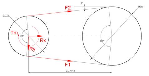
Figure 4: Minor pulley free-body diagram (dimensions given in mm)
The net torque on the smaller pulley corresponds to the motor torque with the design load. This can be calculated as follows:
By substituting the required power P (2641.5 W) and the angular speed of the motor ω motor (188.5 rad/s) into Eq. (4), the torque of 14 N·m on the motor pulley is obtained. This value represents the net torque, which is the difference between the torque produced by F 1 and F 2:

On the other hand, the tensions in the belt are related to the angle of contact and the coefficient of friction, as stated in the following equation (20):
where µ is the static friction coefficient between the belt material and the pulley (assumed to be equal to 0.13) 20, β is the contact angle (167° in the case of the smaller pulley), and α is the angle of the V-groove in the pulley, which is 40° 20). Solving for F 1 and F 2 simultaneously, the results are 212.2 and 59.1 N, respectively.
Beater drum shaft design
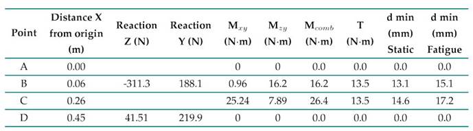
As shown in the free-body diagram in Fig. 5, the reaction forces at bearings B and D were determined by analyzing the equilibrium of the beater drum system 21). The bending moments at the points of interest on the shaft were calculated in the XY and ZX planes. Subsequently, the magnitude of the combined bending moments (M comb ) was determined. The results are summarized in Table II. The distance along the X-axis was measured from point A based on the coordinate system shown in Fig. 5. The drum weight W was estimated to be 490 N, distributed along the drum length (270 mm), while the decortication force on the blade Fe was assumed to be 66 N, applied at the midpoint of the drum. The selected shaft material, given its local availability, was annealed AISI 1020, with S y = 294 MPa, S ut = 394 MPa, and Se ′ = 197 MPa 20, (22. Assuming an initial, arbitrarily selected safety factor of 3, the minimum diameters were determined using static strength formulas and the Goodman criterion for fatigue, as shown in Eqs. (7) and (8), respectively (20). Since the critical points of the shaft (B and C) are free of stress concentrators, the fatigue stress concentration factors k f and k fs were assumed to be 1. A critical shaft diameter of 19.4 mm was obtained for point C (Table II), but a commercial shaft 25.4 mm (1 inch) in diameter was used due to its convenience and commercial availability, resulting in safety factors of 15.8 (static) and 9.7 (fatigue) for the critical point C. Thus, shaft strength was ensured 23).
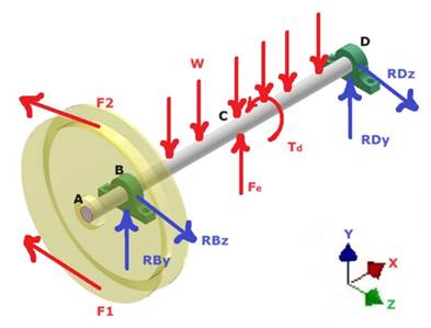
Figure 5: Free-body diagram of the beater drum shaft

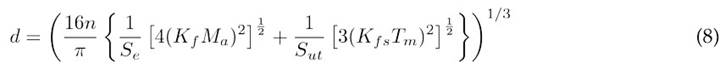
Table II: Summary of beater drum shaft calculations with a safety factor of 3
Through a numerical deflection analysis, the maximum shaft displacement was calculated as 0.13 mm, which is in the range of allowed shaft deflections (0.0762-0.254 mm) according to 20). Therefore, the shaft stiffness requirement was fulfilled.
A load analysis of the shaft indicated that the drum weight is the primary contributor to the bending moment, surpassing the maximum value in the XY-plane by 123 %. Notably, when considering the drum weight alone, the maximum bending moment increases by 18.75 %, highlighting the counteracting effect of F e . This interaction suggests that an increase in F e effectively reduces the net bending stress on the shaft. Consequently, the system exhibits favorable operating conditions, as higher decortication forces do not pose a risk of overloading the shaft and bearings.
Beater drum bearing selection
For selecting the bearings, the radial load on each support was calculated. Table II summarizes the reactions on bearings B and D (a negative sign indicates the opposite direction to the coordinate axis). The combined radial loads were 0.36 and 0.22 kN, respectively. Since there is no axial force component, the bearings only support radial loads. Thus, deep groove ball bearings were chosen as an economical alternative for this application 20).
To calculate the basic dynamic load, it was determined that the bearings should have a lifespan of at least 8000 hours, based on the recommendations of the SKF catalog and bearing in mind that machines used intermittently or for short periods require high reliability 24). This lifespan corresponds to 600 million revolutions, considering a beater angular speed of 1245 rpm.
The basic dynamic load rating of the bearing C is found using the following equation 20:

where P is the equivalent radial load and a is an exponent that depends on the type of bearing (equal to 3 for ball bearings). Through Eq. (9), the minimum dynamic load rating C is 2.61 kN for bearing B and 1.86 kN for bearing D. According to the SKF catalog 24, the bearing designation 61805, with a C value of 4.36 kN, meets the shaft size and basic load capacity requirements for this application.
Feeding roller mechanism design
A leaf-feeding system was proposed which consists of four feeding rollers (Fig. 6a). The two bottom rollers rotate to drive the leaves, while the top ones rotate freely, applying pressure to the leaves as they move through the system. Pressure is guaranteed through four springs located on both sides. Given the variable thickness of the leaves, this tilting system can adjust the opening between the bottom and top rollers to accommodate the thickness of the leaves.
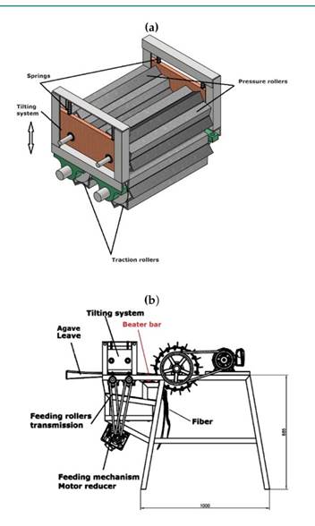
Figure 6: Automatic leaf-feeding system: a) feeding rollers and tilting system, b) feeding roller transmission mechanism (global dimensions given in mm)
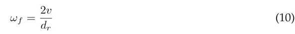
Based on Eq. (1) and the values reported in 11, the optimal leaf feeding speed v was estimated to be 0.7 m/s. Since the effective diameter of the feeding rollers dr was 124 mm, the angular speed of the driver rollers ωf was calculated using Eq. (10), resulting in a value of 105 rpm. To achieve this speed, a belt transmission system was utilized, featuring pulleys with nominal diameters of 55.88 mm (2.2 in) and68.58 mm(2.7in) for the feeding roller and motor shafts, respectively. Additionally, a motor reducer with a speed of 86 rpm and 1/2 hp was employed (Fig. 6b).
To design the tilting system of the feeder rollers, we initially characterized the thickness range of agave leaves from the region of Tambo, Colombia. A random sample of 30 leaves was taken, and the thickness at the base of the leaves —where they are thickest— was measured. This resulted in a range between 20.1 and 49.8 mm. The tilting system should be able to handle these thickness variations.
Based on the research by 25, we determined that a healthy man can exert a hand grip strength (HGS) between 425 and 960.7 N. Since the feeder rollers need to provide at least the same holding force as the human grip while feeding leaves to the machine, we assumed that the compression force for the feeder rollers should match the aforementioned HGS range. By defining a line with displacement and force values of 20 mm and 425 N and 50 mm and 960.7 N (corresponding to the extreme system positions), the slope of the line was determined to be 17.8 N/mm. This slope represents twice the spring stiffness on each side of the roller, as both springs operate in parallel, assuming that the roller and shaft are perfectly rigid. Consequently, the stiffness k of each spring was estimated to be 8.9 N/mm.
To determine the spring dimensions that would result in the calculated stiffness k, the formula reported by 20 was used, assuming a flat-end spring:
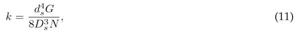
where G is the spring material’s shear modulus (assumed to be 76 923 MPa for steel), d s is the wire diameter, D s is the spring diameter, and N is the number of active coils, which depends on the type of spring ends. After iterating with values of D s and d s while considering a total length of 65 mm and a travel of 35 mm, dimensions suitable for the system’s space and working range of displacement, the spring working parameters were calculated (Table III). These spring parameters achieved the desired stiffness (8.9 N/mm).
Table III: Summary of the springs’ working parameters
Structure verification
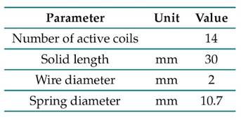
The entire structure was constructed using ASTM A-36 structural steel (S y = 250 MPa) with angles of 38.1 mm (1.5 in) sides and a thickness of 3.175 mm (1/8 in). To verify the safety and stiffness of the structure, a finite element model was developed using the LISA software 26). The model utilized linear 3D beam elements of two nodes and consisted of a mesh of 42 nodes and 61 elements. The mesh size was determined based on displacement convergence criteria, ensuring differences of less than 5 % between successive meshes (Fig. 7).
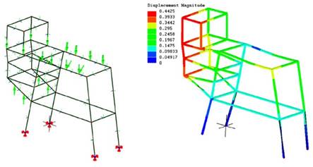
Figure 7: Finite element model of the machine structure, showing a) the mesh and boundary conditions and b) the displacement contours amplified 150 times to facilitate visualization (results given in mm)
The boundary conditions involved constraining translations in the x,y, and z directions at each of the structure’s four supports (Fig. 7a). Moreover, the forces associated with the beater drum weight (490 N), the motor weight (520 N), and the bearing and motor reactions were considered in the model. The analysis revealed a maximum displacement of 0.45 mm, which is less than 0.4 % of the maximum span of the structure, indicating a high structure stiffness. Additionally, a maximum longitudinal stress of 8.0 MPa was obtained, resulting in a safety factor of 29.9, demonstrating the structure’s high strength 23).
Electronic architecture
The developed circuit included three limit switches that serve as sensors to ensure operator safety, as well as start and motor power buttons in the form of two-state switches (ON and OFF). An emergency stop button was also incorporated to shut down the entire electrical system of the machine. It used an electronic circuit based on an ESP32 board, which is a module for Internet of Things applications that features Wi-Fi, Bluetooth, and extensive peripheral support with multiple communication formats 27). The PCB was designed using the Eagle software, starting with a schematic that connected the control pins of the ESP32 board to the circuit components (Fig. 8). The ESP32 module was chosen for its ease of programming when coupled with the Arduino IDE, which is based on open-source hardware and software, making it both time-efficient and user-friendly. Additionally, this module facilitates the future extension of communication and remote monitoring and control capabilities. The final PCB layout, including the connection tracks and components, is shown in Fig. 9.
Figure 8: Control circuit scheme
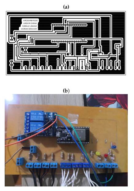
Figure 9: PCB development: a) design layout, b) PCB with components integrated
Construction process
The structural elements, shafts, tilting system, feeder rollers, and beater drum were fabricated using traditional workshop machining processes, including turning, drilling, cutting, and joining through shielded arc metal welding. Fig. 10a illustrates the assembly process, and Fig. 10b shows some initial no-load tests conducted with the assembled machine.
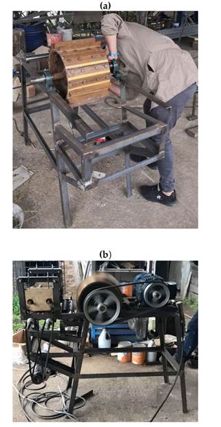
Figure 10: Construction of the machine, a) components assembly, b) no-load test
Results
Preliminary validations
These tests showed that the control system’s switches start and stop the motors correctly. The limit switches activated and deactivated as expected, and the emergency stop button successfully stopped the entire electrical system. In the mechanical power system, the belts and pulleys on both the defibrating and feeding motors functioned correctly during 10 min tests. In each test, an average of 40 ± 2 leaves were decorticated (Fig. 11a), resulting in an average dry fiber production capacity of 31.2 kg/h (COV=0.15). This system effectively handled agave leaves with thicknesses ranging from 20 to 50 mm.Thedefibration system was calibrated to leave a 2 mm clearance between the stationary beater bar and the blades of the beater drum (Fig. 6). Tests with agave leaves yielded optimal and high-quality defibration results. The proposed system successfully fed the agave leaves into the defibrator without risking the operator’s safety.
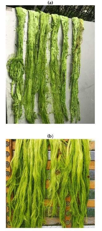
Figure 11: Fiber obtained after decortication in the proposed machine a) as produced by the machine and b) after washing and brushing
Acomparative analysis with other machines in the department from Nariño (Colombia), revealed that, while the prototype leaves some bagasse residues (Fig. 11a), the traditional hand-fed decorticator yields cleaner fibers because operators feed the same leaf multiple times, removing most of the leaf core material. However, the prototype exhibits good defibrating quality, and washing and brushing the f iber maintains it in standards conditions comparable to those of fiber obtained with manual feeding decorticators (Fig. 11b). The total costs of the equipment amount to 1152 USD, which includes material costs, commercial components, and local labor.
Discussion
Sisal, derived from the agave plant, is a biodegradable and sustainable material that offers environmental benefits over synthetic fibers. Unlike synthetic fibers, which are petroleum- based and contribute to long-term environmental pollution, sisal is a natural fiber that decomposes completely, leaving no harmful residues. The cultivation of agave for sisal production is environmentally friendly, as the plant thrives in arid regions with minimal water and chemical inputs, promoting sustainable agricultural practices. Processing agave leaves creates employment opportunities in rural areas of developing countries. However, agave processing can be dangerous, as decorticator machines are manually fed by the operator, which poses some safety risks.
This work presented the development of an agave decorticator with a safe feeding mechanism. The mechanical and electronic design process was completed, resulting in a fully functional design. Since this equipment is intended for rural applications, simplicity and affordability were prioritized. The beater drum speed, pitch, and leaf feeding speed were adapted from 11 and 3, leading to a suitable performance.
While the power requirement was initially estimated using steady-state decortication forces from the literature, real-world conditions introduced transient loads due to startup phases, no-load operation, and variability in leaf dimensions and mechanical properties. To ensure a reliable performance under these fluctuating conditions, we selected a motor with higher available power and applied conservative safety factors to the mechanical design. These measures helped to enhance system robustness and operational flexibility, especially in settings where material consistency cannot be guaranteed.
The novel feeding mechanism effectively mitigates the dangers associated with manual feeding. Our proposal operates at a linear feeding speed of 0.7 m/s, significantly lower than the 27.5 m/s tangential speed of the decorticator cylinder observed in this study —similar values are common in these types of machines 15). This substantial difference in speed drastically reduces the risk of accidents, given that, in hand-fed decorticator machines, the operator introduces leaves directly into the beater drum, leaving insufficient time to react in the event of an emergency or disturbance. Consequently, implementing the proposed system not only enhances operator safety but also improves the reliability of the process.
While traditionally processed fibers are cleaner than those processed by our machine — since operators can feed the same leaf multiple times—, this limitation is not critical, since washing and cleaning are mandatory subsequent processes in the sisal production chain. Preliminary visual inspections of fiber quality suggest comparable results between our prototype and conventional decorticators. However, we acknowledge that more comprehensive quantitative analyses ( e.g., tensile strength testing, fiber length distribution, or purity assessments) would be required to fully characterize any potential differences in fiber quality, which constitutes a limitation of this study. These additional evaluations could be valuable for future comparative studies.
Preliminary tests demonstrated a reasonable machine performance, achieving adryfiberproduction rate of 31.2 kg/h. This rate exceeds the output of sisal decorticators reported by 12) and 3 by 537.9 and 195%, respectively. Nonetheless, it remains significantly lower than the industrial-scale abaca decortication system described by 14, which reported a production rate of 36 576 kg/day (1523.9 kg/h). These results position our machine within an intermediate performance range, substantially more productive than small portable units, yet still offering greater operational safety and accessibility compared to large-scale industrial systems.
Additionally, the cost of the equipment is estimated to be 1152 USD, which is 16% lower than the machine reported by 3 and 53.6% higher than that of 12), who manufactured a portable decorticator on avery limited budget. Future research may be necessary to fully automate the process.
Previous experience suggests that the current fiber extraction efficiency, while satisfactory, can be significantly improved through targeted mechanical and process optimizations 3. The rotary blade mechanism, central to the system’s performance, offers some opportunities for enhancement, particularly through modifications regarding blade geometry, drum clearance, and feed dynamics. Prioritizing the controlled testing of these mechanical parameters appears to be the most practical and cost-effective pathway for near-term improvement. Future research should focus on quantifying the impact of such adjustments on fiber yield and quality, ensuring that performance gains do not compromise the system’s safety and accessibility.
Conclusions
The developed agave decorticator with a safe feeding mechanism was successfully constructed and evaluated in preliminary tests. The machine enhances safety and efficiency for remote and developing regions. Agave processing provides environmental benefits, sustainable agriculture, and rural employment (14). Conclusions The developed agave decorticator with a safe feeding mechanism was successfully constructed and evaluated in preliminary tests. The machine enhances safety and efficiency for remote and developing regions. Agave processing provides environmental benefits, sustainable agriculture, and rural employment 14).
Acknowledgements
Acknowledgements
The authors express their gratitude to Universidad Mariana for providing access to laboratory facilities and the necessary time for conducting this research.
References
License
Copyright (c) 2025 Daniel Suárez-Burbano, Mario A. Rivera-Solarte, Richard G. Moran

This work is licensed under a Creative Commons Attribution-NonCommercial-ShareAlike 4.0 International License.
![]()
From the edition of the V23N3 of year 2018 forward, the Creative Commons License "Attribution-Non-Commercial - No Derivative Works " is changed to the following:
Attribution - Non-Commercial - Share the same: this license allows others to distribute, remix, retouch, and create from your work in a non-commercial way, as long as they give you credit and license their new creations under the same conditions.

2.jpg)