DOI:
https://doi.org/10.14483/23448393.22458Published:
2025-04-15Issue:
Vol. 30 No. 1 (2025): January-AprilSection:
Electrical, Electronic and Telecommunications EngineeringEstudio comparativo de datos empíricos obtenidos de sensores utilizados para medir la distancia de obstáculos
Study Comparing Empirical Data on Sensors used to Measure Obstacle Distance
Keywords:
Internet of Things, Robotics, Obstacle Detection, Ultrasonic Sensor, Infrared Sensor (en).Keywords:
Internet de las Cosas, Robótica, Detección de Obstáculos, Sensor Ultrasónico, Sensor Infrarrojo (es).Downloads
References
N. Kalamain and M. Farrokhi, "Dynamic walking and stepping over large obstacles of biped robots: A Poincaré Map approach," J. Eng. Sci. Tech. Rev., vol. 15, no. 6, pp. 186-200, 2022. https://doi.org/10.25103/jestr.156.23
K. Hu and C. Shidan, "Route planning of intelligent agricultural inspection robots based on improved ant colony algorithm," J. Eng. Sci. Tech. Rev., vol. 16, no. 3, pp. 36-43, 2023. https://doi.org/10.25103/jestr.163.05
N. Amézquita et al., "Preliminary approach for UAV-based multi-sensor platforms for reconnaissance and surveillance applications," Ing, vol. 28, no. 3, pp. 1-33, 2023. https://doi.org/10.14483/23448393.21035
M. William, E. Roberto, and J. Sánchez, "Application of a supervised learning model to analyze the behavior of environmental variables in a coffee crop," Ing, vol. 25, no. 3, pp. 1-15, 2020. https://doi.org/10.14483/23448393.16898
J. L. Garzón, I. Muller, J. M. Winter, A. A. Salles, and C. E. Pereira, "Methodology of cooperative spectrum sensing and dynamic access to the channels in WSN," Phys. Comm., vol. 31, pp. 28-39, 2018. https://doi.org/10.1016/j.phycom.2018.09.001
T. Mohammad, "Using ultrasonic and infrared sensors for distance measurement," in World academy of science, engineering and technology, Sep. 2009, vol. 51, pp. 273-278.
A. M. Joseph, K. Azadeh and B. Rezaul, "State-of-the-art review on wearable obstacle detection systems developed for assistive technologies and footwear," Sensors, vol. 23, no. 5, pp. 1-31, 2023. https://doi.org/10.3390/s23052802
B. Mustapha, Z. Aladin, and K. B. Rezaul, " Ultrasonic and infrared sensors performance in a wireless obstacle detection system," in IEEE 2013 1st Int. Conf. Art. Intell. Modell. Simul., Dec. 2013, pp. 487-492.
A. Rahman, "Precision and accuracy of ultrasonic and infrared laser ToF IoT sensors," J. Infor. Telecomm. Eng., vol. 8, no. 2, pp. 219-226, 2025. https://doi.org/10.31289/jite.v8i2.13406
K. Jia, "Comparative experimental study of infrared distance sensor and ultrasonic distance sensor," in 3rd Int. Symp. Sensor Tech. Control (ISSTC), Jan. 2024, pp. 348-353.
S. Adarsh et al., "Performance comparison of Infrared and Ultrasonic sensors for obstacles of different materials in vehicle/robot navigation applications," in IOP Conf. Ser. Mater. Sci. Eng., vol. 149, art. 012141, Jul. 2016.
J. Sankar, S. Adarsh, and K. I. Ramachandran, "Performance evaluation of ultrasonic and infrared waves on human body and metal surfaces for mobile robot navigation," Mater. Today Proc., vol. 5, no. 8, pp. 16516-16525, 2018. https://doi.org/10.1016/j.matpr.2018.06.007
Z. Khaleel Hind and O. Bashra Kadhim, "Ultrasonic sensor decision-making algorithm for mobile robot motion in maze environment," Bul. Elec. Eng. Infor., vol. 13, no. 1, pp. 109-116, 2024. https://doi.org/10.11591/eei.v13i1.6560
I. Prasojo, P. Nguyen, and S. Nishith, "Design of ultrasonic sensor and ultraviolet sensor implemented on a fire fighter robot using AT89S52," J. Rob. Control, vol. 1, no. 2, pp. 59-63, 2020. https://doi.org/10.18196/jrc.1212
U. Umiatin and A. F. Dendi, "Sharp IR GP2Y0A21 sensor calibration for prototyping application of smart anthropometric system," J. Phys., vol. 2377, no. 1, pp. 1-6, 2022. https://doi.org/10.1088/1742-6596/2377/1/012026
C. Technologies, Product User's Manual-hc-sr04 Ultrasonic Sensor, Cytron , 2013. [Online]. Available: https://web.eece.maine.edu/~zhu/book/lab/HC-SR04%20User%20Manual.pdf
C. Technologies, HC-SR04 User Guide, Cytron, 2020. Online]. Available: https://www.mpja.com/download/hc-sr04_ultrasonic_module_user_guidejohn.pdf
C. Technologies, Data sheet GP2Y0A021YK, Cytron, 2020. Online]. Available: https://files.seeedstudio.com/wiki/Grove-80cm_Infrared_Proximity_Sensor/res/GP2Y0A21YK.pdf
How to Cite
APA
ACM
ACS
ABNT
Chicago
Harvard
IEEE
MLA
Turabian
Vancouver
Download Citation
Recibido: 8 de julio de 2024; Revisión recibida: 2 de diciembre de 2024; Aceptado: 15 de marzo de 2025
Abstract
Context:
Electronic sensors play a crucial role in different applications such as robotics or industrial or home automation. Sensors can measure essential environmental variables in order to feed digital signal processing algorithms and perform actions more efficiently. The sensors used for distance measurements follow different approaches. However, it is difficult to find a study with performance comparisons.
Method:
An empirical study was performed to evaluate and compare the performance of ultrasonic and infrared sensors in frontal and lateral detection situations while considering distance and angle variations.
Results:
The results show that the ultrasonic sensor detects the distance with good accuracy along its operational range. However, the distance measure is inaccurate when the obstacle is not orthogonal to the sensor. The ultrasonic sensor showed high accuracy in long-range, frontal obstacle detection, while the infrared sensor performed better at short distances with angled obstacles. Statistical analysis confirmed strong linear correlations, especially for the ultrasonic sensor, supporting the complementary use of both sensors in distance measurement applications.
Conclusions:
An evaluation of ultrasonic and infrared sensors for distance measurement in applications involving robotics and the Internet of Things revealed that the former are more reliable for distant, orthogonal obstacles, while the latter perform better at short distances on angled surfaces, highlighting their complementary strengths and the need for future improvements to address environmental sensitivity and detection limitations.
Keywords:
Internet of Things, robotics, obstacle detection, ultrasonic sensor, infrared.Resumen
Contexto:
Los sensores electrónicos tienen un papel crucial en diferentes aplicaciones como la robótica o la automatización industrial o doméstica. Los sensores pueden medir variables ambientales esenciales para alimentar algoritmos digitales de procesamiento de señales y realizar acciones de una manera más eficiente. Los sensores que se utilizan para mediciones de distancia siguen enfoques diferentes. Sin embargo, es difícil encontrar un estudio con comparaciones de desempeño.
Método:
Se realizó un estudio empírico para evaluar y comparar el rendimiento de sensores ultrasónicos e infrarrojos en situaciones de detección frontal y lateral, considerando variaciones de ángulo y distancia.
Resultados:
Los resultados muestran que el sensor ultrasónico detecta la distancia con buena precisión a lo largo de su rango operacional. Sin embargo, la medida de distancia se torna inexacta cuando el obstáculo no está ortogonal al sensor. El sensor ultrasónico mostró gran precisión en la detección de largo alcance de obstáculos frontales, mientras que el sensor infrarrojo se desempeñó mejor en distancias cortas con obstáculos en ángulo. Un análisis estadístico confirmó la presencia de correlaciones lineales fuertes, especialmente en el caso del sensor ultrasónico, lo que respalda el uso complementario de ambos sensores en aplicaciones de medición de distancias.
Conclusiones:
La evaluación de sensores ultrasónicos e infrarrojos para la medición de distancias en aplicaciones que involucran robótica y el Internet de las cosas reveló que los primeros son más fiables para obstáculos distantes y ortogonales, mientras que los segundos funcionan mejor en distancias cortas y con superficies en ángulo, resaltando sus fortalezas complementarias y la necesidad de futuras mejoras para abordar la sensibilidad ambiental y otras limitaciones de detección.
Palabras clave:
Internet de las Cosas, robótica, detección de obstáculos, sensor ultrasónico, sensor infrarrojo.1. Introduction
Scientific advances have allowed helping people in their daily life and work, as well as improving their safety. Advances in robotics and the development of associated sensors are fundamental to improving the efficiency of human activities in different contexts (e.g. industrial, commercial, and educational, among others). The use of sensors to detect obstacles or objects is key for some applications requiring autonomous vehicles (drones or ground robots) to perform risky tasks such as deactivating land mines or even rescuing living beings in earthquakes or landslides. In this vein, it is necessary to understand the accuracy of measurements carried out by ultrasonic and infrared sensors in order to adjust the operation of autonomous vehicles. Moreover, this type of sensors can be used to assist in and improve different tasks like obstacle avoidance for bipedal robots 1, route planning for agricultural inspection robots 2, unmanned aerial vehicle control 3, and environmental analysis in coffee crops 4. In the context of cognitive device operation, the accuracy of sensor measurements is a critical factor in decision-making processes 5.
Some work has been carried out to investigate the operation and accuracy of ultrasonic and infrared sensors, as detailed below.
The study by 6 presents a method that considers the infrared reflectance properties of a surface to estimate distance. However, it requires other sensing modalities to obtain information on the distance to the obstacle. Experiments indicated that this type of low-cost sensor can provide reliable distance measurements, and the results showed agreement between the Phong illumination model and real data from testing.
The work by 7 describes the use of wearable obstacle detection systems for safe human locomotion. The focus of this review is gait-assisting wearable sensors and hazard detection for pedestrians. This study analyzes the sensors used for detecting risks to pedestrians, highlighting the major advantages and disadvantages of each approach, analyzing the sensors and hardware components used, and explaining their potential for improving the quality of life of individuals with locomotor disabilities.
A performance study of ultrasonic and infrared sensors in a wireless obstacle detection system is conducted in 8. These sensors aim to enhance walking safety by identifying the risk of tripping and providing corrective feedback.
In 9, ultrasonic and infrared sensors are evaluated with the purpose of determining their operational performance regarding distance measurement. However, aspects such as detection angle and statistical correlation analysis are not addressed, as the focus is limited to validating their basic functionality.
In 10, the operation of infrared sensors is analyzed while considering the influence of light. The performance of ultrasonic sensors under the effects of temperature and humidity is also evaluated.
A comparison between ultrasonic and infrared sensors is made in 11 while considering obstacles with different materials. Obstacle distance detection performance is evaluated for cardboard, paper sheet, sponge, wood, plastic, rubber, and tile. This study is significant in that it aids in selecting the best combination of sensors to achieve good results in robotics applications.
In 12, an evaluation of ultrasonic and infrared sensors for mobile robot navigation is carried out. This work considers the wave interaction between the human body and metal surfaces. In terms of the root mean squared error, the results show complementary behaviors for the two sensors used, evidencing the need for data fusion strategies to minimize the positional error of obstacles for effective robotic navigation 12. In addition, the motion efficiency of a mobile robot equipped with an ultrasonic sensor decision-making algorithm is studied in 13, considering the time required to follow a predefined test path.
Ultrasonic and infrared sensors are very popular in some applications. For example, the design and reaction time required to find targets for a firefighter robot equipped with these types of systems are described in 14. Said robot can assist with activities that pose serious risks to human firefighters.
Most works have failed to present a detailed study on the performance of ultrasonic and infrared sensors for frontal or lateral situations 15. Although previous reports have compared these sensors under different conditions, they often focus on specific applications or general accuracy metrics without thoroughly analyzing their performance under varying obstacle orientations. This study differs by systematically evaluating these sensors in both frontal and lateral detection scenarios while considering the impact of angle and distance variations. Additionally, we incorporate a detailed correlation analysis between real and estimated distances, which is often overlooked in similar studies. This approach allows for a better understanding of each sensor's operational limits and its suitability for different applications. The findings not only complement existing research but also challenge certain assumptions regarding the accuracy and reliability of these systems under non-ideal conditions. In some cases, the literature is more focused on the study of the robotic system in general, without considering the effect of the sensors and the correlation of the measurements.
In this context, the proposed work provides a description of ultrasonic and infrared sensors which considers different experiments for detecting the distance of objects in frontal and lateral situations. A data analysis is performed to compute correlation coefficients, comparing the real distance against the estimated value. On the other hand, the HCSR04 ultrasonic sensor and the GP2Y0A021YK infrared sensor are compared with the purpose of determining the best option for specific use cases. This research aims to highlight the circumstances in which the sensors are effective while considering their use limits, as described in the existing data sheets. This work is organized into five sections, i.e., 1) introduction, 2) methodology, 3) results, and 4) conclusion.
2. Methodology
2.1. Sensors and characteristics
Two sensor types (ultrasonic and infrared) were used in this work with the aim of identifying their performance in distance detection.
The ultrasonic sensor (HC-SR04), by Corporate Computer, has an operating range of 2 to 400 cm. It has two inputs and two outputs for VCC, TRIG, ECHO, and GND signals. The angle to the normal line of the obstacle surface cannot exceed 15°. Therefore, in this work, the obstacle had to be orthogonal to the surface of the sensor, i.e., at a right angle (90°) to the sensing surface of the sensor. The ultrasonic sensor was fed with 3 V and was connected to ESP8266 device. The trigger input (TRIG) was used to send a series of pulses over eight cycles clocked at 40 kHz.
Fig. 1 shows the basic operation of the sensor. The ECHO output measures the time interval between sending the TRIG signal and receiving the ECHO signal, so the pulse width delivered by the output is used to determine the distance 16.
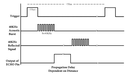
Figure 1: Timing diagram of signals in the ultrasonic sensor (17)
The ultrasonic sensor sends a TTL pulse with a duration of 10 us via the TRIG pin. A set of pulses clocked at 40 kHz are sent at the end of the TTL pulse (acoustic burst). Finally, the ECHO pin recovers the transmitted signal, and it sends a pulse with a specific width, which can take values from 150 to 25 ms. The distance d can be calculated using Eq. (1).
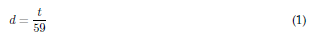
where, t is the time interval between sending the TRIG signal and receiving the ECHO signal (i.e., the space between the acoustic bursts and the reflected signal). Two scenarios were analyzed for the ultrasonic sensor: the first with the obstacle frontally aligned to the sensor (frontal) and the second with the obstacle non-frontally aligned (lateral), in order to obtain a map with the view field of sensor.
The GP2Y0A21YK0F infrared sensor by Sharp has an analog output and is controlled and fed by the ESP8266 device. The Vo output measures the time interval between sending the trigger signal and receiving it. Thus, the distance is calculated by the pulse width delivered by the output 18. The sensor performs various measurements, as shown in Fig. 2.
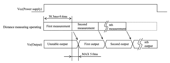
Figure 2: Timing diagram of signals in the infrared sensor (18)
To obtain the distance between sensor and obstacle, the equation to convert the ADC value into the estimated distance was determined. The theoretical curve provided by the manufacturer is shown in Fig. 3. It relates the distance to the object with the output voltage.
Furthermore, the behavior of the infrared sensor was determined. To this effect, a flat obstacle was positioned orthogonally to the sensor and then moved centimeter by centimeter. Fig. 4 shows the results of the measured distances vs. the ADC values for the experiment. These results provided the data curve and its representative Eq. (2).
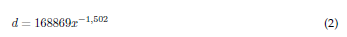
This equation was used for the first study of the sensor. The numerical value given by the sensor was recorded during this research and compared against a theoretical distance. x represents the value generated by the ADC converter, which is denoted as gp2y0a21Val in the program environment.
2.2. Experiments
The sensor's behavior was studied in two scenarios: frontal and lateral. Experiments were conducted in a controlled environment within an Internet of Things (IoT) laboratory, which has an approximate area of 6 x 6 m. No additional objects were present which could interfere with the measurements. The obstacle used was a 22 x 27 cm rectangle. In addition, for the infrared sensor, a flat white surface was used to optimize wave reflection.
To ensure the repeatability and precise control of distances and angles, a programmable system based on the ESP8266 was used. This system followed predefined trajectories, allowing for systematic measurements. Markers were placed on the ground at regular intervals to verify the actual distances between the sensor and the obstacle. Table I details the number of measurements taken for each point, with a total of 47 positions in 2 cm steps (0 to 92 cm) for the infrared sensor and 93 positions in 5 cm steps (0 to 460 cm) for the ultrasonic sensor. In this work, a test refers to an experiment involving measurements (10 per position point), and a position point is one of the possible locations of the obstacle relative to the sensor.
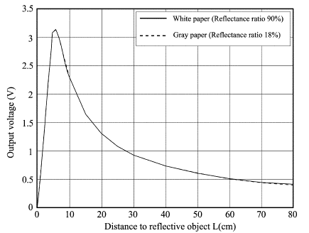
Figure 3: Timing diagram of signals in the ultrasonic sensor 18
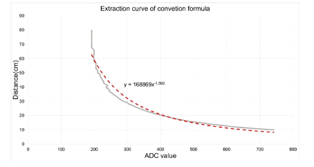
Figure 4: Computed and measured distances for different values of the ADC of sensor
Table I: Details on the number of experiments
Type of sensor and situation
Infrared sensor, lateral
Infrared sensor, frontal
Ultrasonic sensor, lateral
Ultrasonic sensor, lateral
Number of tests performed
5
5
5
5
Number of
measurements per
10
10
10
10
point at each test
Total number of
measurements
50
50
50
50
per point
Total number of position points
47
47
93
93
Total number of measurements per scenario
2350
2350
4650
4650
2.2.1. Frontal situation
The first study focused on readings of the distance between the sensors and a frontally positioned obstacle. A class was created for each type of measurement and sensor. For each test, the program computed the average while considering 10 detected values to obtain a single measurement, with the purpose of reducing the impact of sensor fluctuations. For each measure in the ultrasonic sensor, the distance from the sensor to the obstacle was varied from 0 cm to 460 cm in 5 cm steps. The program recovered the propagation time in milliseconds, as well as the measured and actual distance in cm. For the infrared sensor, the distance between sensor and obstacle was varied from 0 cm to 92 cm. The maximum distance was that indicated by the manufacturer plus 15 % for both sensors. The program was used to extract the digital value of the sensor with the measured distance and compare it against the actual values. The values were stored in a dynamic array and presented as a text file in the following format: time; d_distance; d_Realdistance.
2.2.2. Lateral situation
To determine the detection response of sensors to non-frontal situations, the obstacle must be placed in the extension of the sensors and diagonally displaced to the right.
In this experiment, each obstacle is moved along the corresponding range, i.e., from 0 to 460 cm (5 cm steps) for the ultrasonic sensor and from 0 cm to 92 cm (2 cm steps) for the infrared sensor. The program sends a notification when the obstacle is out of the measurement range and becomes invisible for sensor. Fig. 5 shows the positioning of the sensor and the obstacle. A real measurement of the distances is performed for each point and fed to the program. This process is repeated for the subsequent distances. The program computes the sensor's angle with respect to the obstacle. Here, a right angle indicates whether the sensor is able to detect objects located along the diagonal, which is analogous to the left diagonal by the symmetry of sensors.
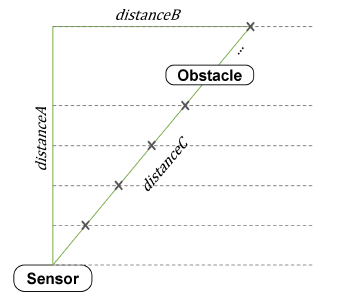
Figure 5: Lateral positioning of the obstacle
The values are stored in a dynamic array, and they are presented as a text file in the following format: d_time; distanceA; distanceB; distanceC; angle. The angle is obtained using Eq. (3).
3. Results
3.1. Ultrasonic sensor
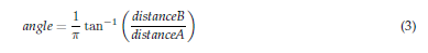
The HC-SR04 sensor can detect an obstacle if it is orthogonal to its field of view, with a theoretical angular tolerance of 15°. However, the sensor cannot identify an obstacle that is not orthogonal. The sensor is directional and provides accurate distance estimations in frontal scenarios, as shown in Fig. 6a. The distance measured in frontal situations (0° angle) shows excellent correspondence with the real distance, forming a linear relationship. Moreover, in most measurements (Fig. 6b), the error remains below 1 %, except for the estimation of shorter distances (0 to 90 cm), where it exceeds 1 % but stays below 5 %.
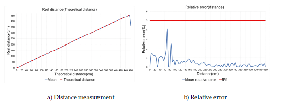
Figure 6: Ultrasonic sensor in frontal situations
Studying the vision range allows understanding the sensor's ability to detect diagonal obstacles (Fig. 7). The results show better distance detection when the obstacle is located frontal to the sensor at large distances close to the 400 cm limit. This has to do with the directivity of the ultrasonic sensor in radiating the power of signal, provided that it is not disturbed by its environment. Distance estimation can be performed at shorter distances, but only when the obstacle is diagonally positioned relative to the sensor. For example, it is possible to detect objects at 200 cm and 10°, or at 50-150 cm and 20°.
Figure 7: Ultrasonic sensor in lateral situations
The values show a defined tendency, without significant variations. Measurement accuracy is also a strength of this sensor; the error is low - almost negligible - along its range of use. The operating range specified by the manufacturer is therefore validated. However, the sensor is capable of operating beyond the theoretical limit.
Some advantages of the ultrasonic sensor include an operating range of 2 to 400 cm, good accuracy, high directivity, and ease of use. On the other hand, one of its drawbacks is its inability to detect obstacles that are significantly offset from its field of view, a phenomenon that becomes more pronounced as the distance increases.
3.2. Infrared sensor
The GP2Y0A021YK infrared sensor does not allow for obstacle detection at long distances when compared to its ultrasonic counterpart, since its detection range is limited to 80 cm according to the manufacturer's data. However, the sensor cannot be used throughout the recommended operating range. The experiment conducted in this study showed that the sensor can only detect distances between 10 and 60 cm. The use of Eq. (2) implies some error, which is more considerable for distances between
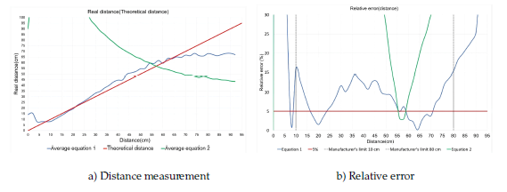
Figure 8: Infrared sensor in frontal situations
Fig. 8 presents some tests carried out on the infrared sensor, altering the distance to the obstacle in frontal positions. Within the operating range (10 to 80 cm), estimation via Eq. (2) is adequate for applications requiring lower accuracy. However, in some tests (e.g., 10, 37, 45, or 80 cm), the error is high (close to 15%). As shown in the figure, distance measurement errors become excessively high outside the operating range.
On the other hand, Fig. 9 presents the sensor's performance in lateral scenarios. This sensor provides accurate distance estimations at angles of up to approximately 20° along most of its operating range. Even at short distances, the angle can reach nearly 30°. Different measures were taken, and a good correlation between them was observed. The red line in Fig. 9 shows the average for all measurements, representing the estimation tendency of the sensor.
The main advantage of the infrared sensor is its good detection of obstacles in lateral situations. However, it has some drawbacks, such as difficulties in obtaining a realistic equation for distance estimation, medium accuracy along the theoretical operational range, and low estimation distances (80 cm maximum limit).
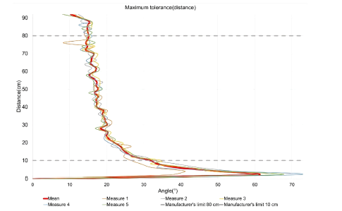
Figure 9: Infrared sensor in lateral situations
3.3. Statistical study
Using Python, several statistical studies were performed. A linear correlation was established between the two sensors in order to quantify their linear relationship. Fig. 10 presents a scatter diagram with linear adjustment, with the ultrasonic sensor on the horizontal axis and the infrared sensor on the vertical one.
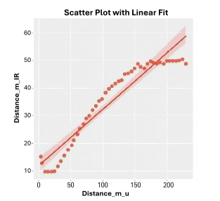
Figure 10: Scatter diagram with linear adjustment
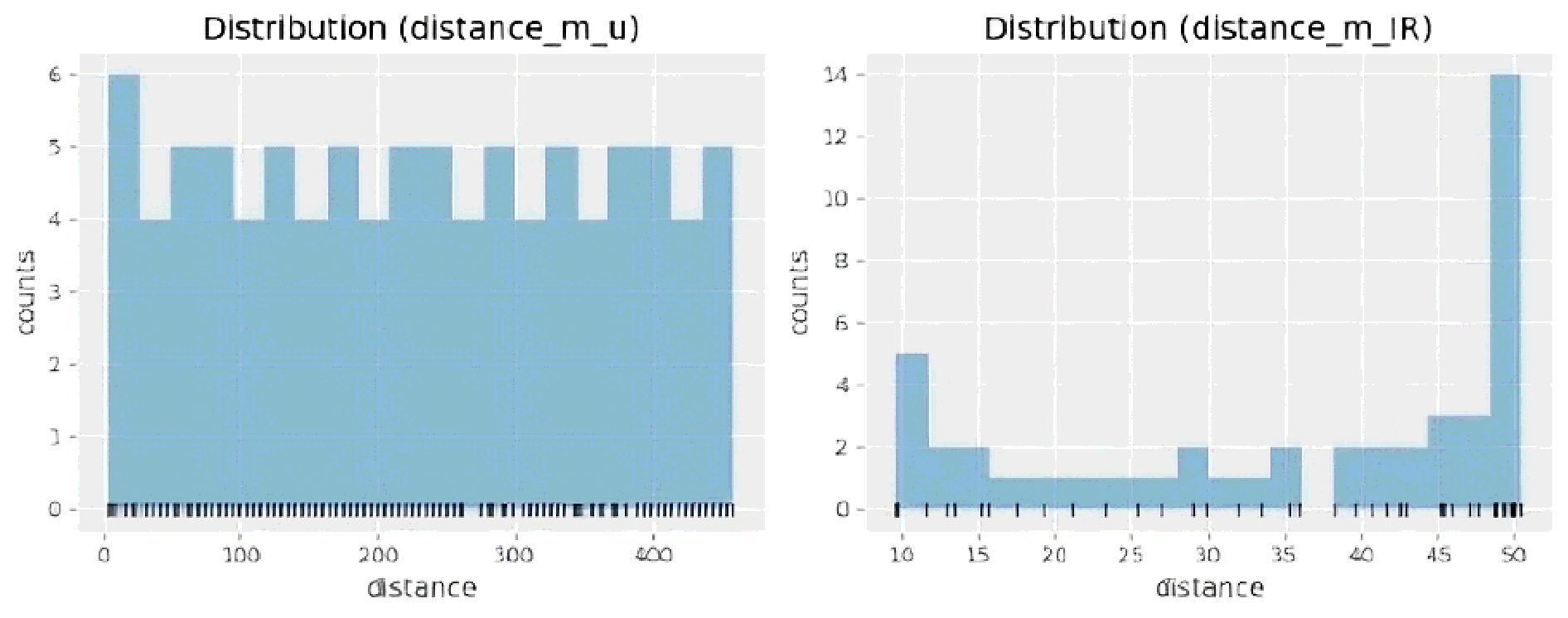
The two mean distances increase simultaneously at a constant rate. The scatter plot in Fig. 10 shows a positive linear relation between the distance variables measured by the sensors. However, this is only the case for distances between 10 and 50 cm measured by the infrared sensor. Outside this range, the relation is not exactly linear anymore. In this vein, the different correlation coefficients were determined, and a distribution plot was elaborated for both sensors (Fig. 11). This plot shows that the data distribution has a non-normal tendency and is slightly more uniform.
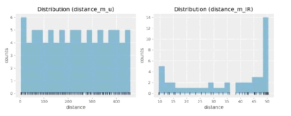
Figure 11: Distribution of values for both sensors
Fig. 12 presents the results of a study conducted to evaluate the distribution of the residuals, which are aligned along a straight line. However, very slight biases can be observed in the tails. The data lie close to the red line, indicating a linear correlation.
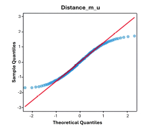
Figure 12: Quantile diagram for the ultrasonic sensor
An analysis was performed to qualify the results and compute the correlation coefficients with several methods: Pearson, Spearman, and Kendall. In all cases, a more sensitive result was observed with regard to the extreme values, as well as a good correlation for most values.
For the ultrasonic sensor, the linear association is very high for all three methods, which confirms that the measured results are close to the theoretical values. The correlation coefficients computed for the ultrasonic sensor are as follows:
-
Pearson correlation: 0.999
-
Spearman correlation: 0.999
-
Kendall correlation: 0.998
On the other hand, the infrared sensor exhibits a lower linear association than its ultrasonic counterpart, but it remains over 90 %, which is also a high value. The correlations for the infrared sensor are presented below:
-
Pearson correlation: 0.952
-
Spearman correlation: 0.982
-
Kendall correlation: 0.926
Good results were obtained since the correlation for the infrared sensor was evaluated along its operating range, which shares many similarities with that of the ultrasonic sensor. It is possible to obtain lower correlations by comparing the infrared sensor used against other alternatives with different operating ranges.
4. Conclusions
In this work, the performance of ultrasonic and infrared sensors was evaluated in various situations, with the aim of understanding their operational characteristics and accuracy in measuring the distance to obstacles. This information is crucial for applications involving robotics and the Internet of Things, since precise obstacle distance measurements are fundamental for ensuring safe navigation, optimizing route planning, and enabling real-time decision-making in autonomous or semi-autonomous systems.
The results indicate that the ultrasonic sensor is the most effective for dealing with distant obstacles, provided that they are orthogonally oriented. However, when measuring shorter distances with obstacles that are not necessarily orthogonal, the infrared sensor exhibits a better performance. In other words, both sensors can complement each other to enhance the performance of devices such as robots or automated systems.
Nevertheless, it is important to highlight that infrared sensors are more susceptible to environmental factors, such as material reflectance variability, which can introduce measurement errors. On the other hand, ultrasonic sensors may struggle with detecting inclined or small surfaces. These limitations should be considered in future implementations and studies, exploring calibration methods or compensation algorithms to improve the accuracy of both devices.
The comparison between ultrasonic and infrared sensors underscores the need to consider application-specific trade-offs such as range, response time, and environmental conditions. The careful selection of either sensor - or indeed the combination of both - has been shown to substantially enhance system reliability and efficiency. A hybrid approach can often provide a more robust solution by leveraging the strengths of each technology in order to overcome their individual limitations.
Acknowledgements
5. Acknowledgements
The authors express their gratitude to Unidades Tecnológicas de Santander (UTS) and Polytech Aix-Marseille Université for their support during this research and within the framework of international academic collaboration between France and Colombia.
References
License
Copyright (c) 2025 Johan Leandro Téllez-Garzón, Jorge Saúl Fandiño-Pelayo, Bernard Antoine , Mazzini Giovanni

This work is licensed under a Creative Commons Attribution-NonCommercial-ShareAlike 4.0 International License.
![]()
From the edition of the V23N3 of year 2018 forward, the Creative Commons License "Attribution-Non-Commercial - No Derivative Works " is changed to the following:
Attribution - Non-Commercial - Share the same: this license allows others to distribute, remix, retouch, and create from your work in a non-commercial way, as long as they give you credit and license their new creations under the same conditions.

2.jpg)