DOI:
https://doi.org/10.14483/23448393.2115Published:
2008-11-30Issue:
Vol. 14 No. 1 (2009): January - JuneSection:
Science, research, academia and developmentTutorial Para El Diseño De Filtros Digitales Fir Sobre Fpga
Tutorial for the Design of FIR Digital Filters over FPGA
Keywords:
Filters, FIR, FPGA, VHDL. (es).Downloads
References
ALTERA Corp., "FPGAs Provide Reconfigurable DSP Solutions", White Paper, August 2002, version 1.0.
ALTERA Corp., "Implementing FIR Filters in FLEX Devices", Application Note 73, February 1998, version 1.01
ALTERA Corp., "Using PLDs for High-Performance DSP Applications", White Paper, February 2002, version 1.0.
G. Proakis and D. Manolakis. "Tratamiento digital de señales", Primera Edición, Prentice Hall. 1998.
K. Ogata. "Sistemas de Control en Tiempo Discreto", Segunda Edición, Prentice Hall. 1996.
LAHUERTA Aguilar, Eduardo; MEDRANO Sanchez, Carlos y RAMOS Lorente, Pedro, et al. Implementación de un filtro digital en VHDL. Universidad de Zaragoza, España.
MELGAREJO, Miguel y PIRAJAN, Alexis, et al. Filtro FIR adaptativo sobre celdas lógicas programables FPGA. En revista Ingenieria, Universidad Distrital. Bogota, Colombia. 2000.
R. Hamming. "Digital Filters", Editorial Prentice Hall. 1999.
R. N Vera. "Sistemas de Transmisión", Segunda Edición, Mc Graw Hill. 1998.
S. Haykin. "Señales y Sistemas". Primera Edición, Prentice Hall. 1997.
VERA Lizcano, Mario; VEJARANO, Gustavo y Velazco Medina, Jaime, et al. Diseño de funciones DSP usando VHDL y CPLDsFPGAs. En revista: Ingenieria y Competitividad, Universidad del Valle. Cali, Colombia. 2006.
XILINX Corp., "Distribuited Arithmetic FIR Filter".Marzo 2002.
How to Cite
APA
ACM
ACS
ABNT
Chicago
Harvard
IEEE
MLA
Turabian
Vancouver
Download Citation
Ciencia, Investigació, Academia y Desarrollo
Ingeniería, 2009-00-00 vol:14 nro:1 pág:13-17
Tutorial for the Design of FIR Digital Filters over FPGA
TUTORIAL PARA EL DISEÑO DE FILTROS DIGITALES FIR SOBRE FPGA
César Augusto Hernández Suarez
Magíster en Ciencias de la Información y las Comunicaciones de la Universidad Distrital. Docente de Planta de la Universidad Distrital.
Edwar Jacinto Gómez
Estudios de Maestria en Ciencias de la Información y las Comunicaciones de la Universidad Distrital. Docente de la Universidad Distrital.
Octavio José Salcedo Parra
Docente de Planta de la Maestría en Ciencias de la Información y las Comunicaciones de la Universidad Distrital.
Abstract
This article presents a different and simple methodology in the design and implementation of digital filters with finite impulsional response, over a reconfigurable architecture like FPGA XC3S200. In this development were used CAD tools as FIR toolbox and ISE of Xilinx, obtaining with that results in record time, optimization in the hardware resources used and good performance in frequency, desirable characteristics in the development of systems oriented to the digital signal processing.
Key words:
Filters, FIR, FPGA, VHDL.
Resumen
Este artículo presenta una metodología diferente y sencilla en el diseño e implementación de filtros digitales con respuesta impulsional finita, sobre una arquitectura reconfigurable como la FPGA XC3S200. En este desarrollo se emplearon herramientas CAD como "FIR toolbox" e "ISE" de Xilinx, obteniendo con ello resultados en tiempo record, optimización en cuanto a los recursos de hardware utilizados y un buen desempeño en frecuencia, características deseables en el desarrollo de sistemas orientados al procesamiento digital de señales.
Palabras claves:
Filters, FIR, FPGA, VHDL.
1. INTRODUCTION
The digital signal processing is an area of electronics that has had great advances in the last years due to technological developments in hardware. Today it plays an important role in areas such as communications, circuit design, acoustics, voice processing and energy regeneration and distribution systems, for this reason has been conceived an architecture of digital filter of high capacity y computation speed, obtaining with this more accuracy compared with the analogical circuits and the analogical signal processing systems.[9]. Other advantages of the digital filters with respect to its similar analogical filters are their small size, efficiency and the possibilities of a fast reconfiguration in its tasks. This being supported by technologies with high scale of integration [7].
The digital signal processors (DSPs) are used to implement many of the DSP applications, among others are the digital filters. Nevertheless, even though the DSPs are programmable through software, the architecture of the hardware of these is not flexible; on the contrary is fixed, which is noted for example by the fixed number of multiplicator accumulator blocks (MAC), or the width of the data bus. This constitutes a limitant for the DSPs with respect to reconfigurable architectures with the CPLDs and the FPGAs [11].
The CPLDs-FPGAs circuits provide a reconfigurable and efficient solution to implement DSP applications as the digital filters. These circuits can reach a higher throughput and more data processing potency than the DSPs [11].
This article pretends to expose a different methodology in the design and implementation of FIR digital filters by the use of CAD tools as FIR toolbox and ISE of Xilinx. The methodology proposed pretends to reduce considerably the time required to perform a FIR digital filter, and to optimize the available hardware resources in the FPGA XC3S200, selected as programmable logic device to implement such solution.
2. FILTER FIR DESIGN
The digital filter to be designed is a FIR filter (finite impulsional response). The FIR filters have two main advantages with respect of the IIR filters (of infinite response) [6]. The first one is they can be designed with lineal phase, so that they do not phase present distortion. Also, they are unconditionally stable due to the fact that their transference function has only zeros. Nevertheless, an IIR filter requires a minor number of coefficients than a FIR filter [6].
A FIR digital filter has a response to the impulse of finite duration that can be expressed mathematically as:

Where N is the order of the filter. This expression indicates that the actual output value of an FIR filter is the function of actual entrance and of the N preceding entrances. In effect, the system behaves as a window. In the same way, an FIR filter can be described by its transference function as:

In other words:
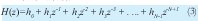
The roots of this polynomial are the zeros of the filter. Therefore, the design problem of the FIR filters is simply to determine the N coefficients h(n) from a specification of the desired response frequency (HD(ω)).
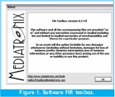
In this methodology the free software "FIR toolbox" developed by the company Mediatronix is the tool responsible to determine the coefficients h(n) of the filter, from configured parameters by the designer. This tool facilitates the development of this process and provides total compatibility with programmable logic devices. (See Fig. 1).
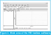
In figure 2 can be observed the work area of the tool "FIR toolbox".
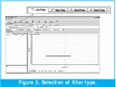
In the upper options can be selected the type of filter desired: low pass, high pass, band pass o band stop, with their respective cut frequencies at less than 3dB. See figure 3.
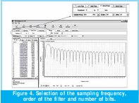
Next will be determined the sampling frequency, the order of the filter and the amount of bits. To select the sampling frequency the designer has to take in consideration the characteristics of the analog - digital convertor (ADC) and the final application of the filter. To select the order of the filter is necessary to take in consideration that it can affect the wideband of the filter. The number of bits determines the precision of the mathematical calculations, and thereby the designer based on experience will select the amount of bits according to the desirable performance of the filter. See Figure 4.
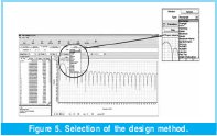
Next is selected the method of design from which will be calculated the coefficients of the FIR filter. See Figure 5.
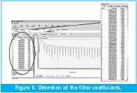
At last, the design option is pressed to obtain the fixed points to obtain a simple implementation that facilitates the calculations within the programmable logical device. Nevertheless, the tool provides a list of the coefficients with their representation in floating point and their respective fixed point representation, whose transformation depends on the amount of bits selected in the preceding procedure. See Figure 6.
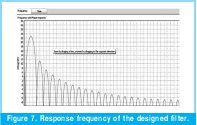
The tool also provides the option to verify the behavior in time and frequency of the designed filter, as for their cut frequencies and their phases, as observed in Figure 7.
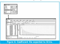
In last term, the archive of the filter coefficients with extension COE is exported, as shown in figure 8. This archive is compatible with the ISE from Xilinx, which allows a direct and simple implementation.
3. REALIZATION OF THE FILTER IN VHDL
For the implementation of the designed filter with the "FIR toolbox" tool and the software ISE 8.1 of Xilinx, the FPGA Spartan3 XC3S200 was selected. The programming of this FPGA from a COE extension archive generated before was very simple. In first instance a new project was created as shown in Figure 9.

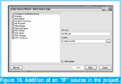
Once the project was created a new source was added, but this time was not selected the option "VHDL module" but IP (Coregen & Architecture Wizard)" as indicated in Figure 10.
The IP source is an intellectual property module (IP: Intellectual Property), that allows the realization of fast designs optimizing the systems for specific applications as the one that is occupying us in this case.
Within a great variety of modules offered by the IP source, we selected "Distributed Arithmetic FIR Filter", in other words a FIR filter with a parallel and massive hardware, which will use more gates than a FIL filter realized with an architecture based on MAC ( as a DSP), but with a higher processing level.
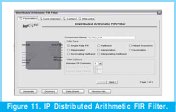
After that, the amount of channels of the filter is configured, and the interpolation of the entrance data of it. According to the analog digital convertor used as entrance to the system, and its functioning mode, the type of data conditioning most appropriate was selected, as shown in Figure 11.
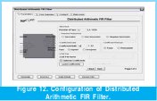
After the preceding step, depending on the filter grade, the amount of storing elements (Taps) is configured, the format of the output data and the width of the job word of the filter, as of the charge of the coefficients of the archive. All the preceding depends on the parameters used to calculate the digital filter in the "FIR toolbox" tool. See Figure 12.
It is also important to note that in this point is given the option to choose among fixed coefficients or reconfigurable coefficients which will give the option to make adaptive filters, or to apply control strategies as evolutive hardware or any other type of implementation that has as base an equation in differences with reconfigurable coefficients.
The last thing to do is choose the width of the entry data, if coming from the convertor with or without sign, also if fan implementation is going to be realized, serial or parallel, and if it will have a general reset to restart the system in case it is necessary, also is given the option to put an exit registry in the exit of the system.
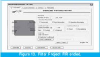
After having the core of the filter totally configured and loaded with the indicated coefficients, it is included in the project created in the ISE, in this case was included as a block in the graphic tool of this suite. See Figure 13.
4. RESULTS
Once ended the implementation within the device a report of the use of it is shown, and in Figure 14 can be observed that only 17% of the available resources in the FPGA Spartan 3 of 200 thousand gates was used.

It is important to note that the order of the designed filter is 50, which is very high and brings as consequence the great amount of gates used in the implementation. This number of gates can be reduced considerably by reducing the order of the filter.
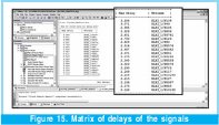
Another of the characteristics of this filter of great relevance is the maximum work velocity that limits the entry frequency of the signal to be filtered, as shown by a delay matrix, in which a list is made of the maximum times of transportation of the different signals in the implementation. In this case the maximum delay is 3.2 nanoseconds, which gives a maximum frequency of work of about 312 megas that divided by the 16 cycles that it takes to do each calculation of the new exit of the filter gives us the maximum sampling frequency, which is 19.5 megahertz , tests that will be made later. See Figure 15.
After implementation we proceed to realize a simulation of the system, for which is generated an archive of hundreds of simulation vectors, which can be created in excel or in Matlab with the signals that enter to our system, this archive is called Test bench. When trying to simulate a complex digital system it has the problem to simulate and verify the results of the system in higher ranges of time, and in this case we use a tool called ModelSim, that allows us to make simulations with big advantages, as for example a type of simulation that transforms digital data into analog, which can give an idea of what really is happening with the designed system.
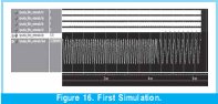
In Figure 16 can be observed a first simulation. In the upper part can be seen the clock signals and control of our digital system, which in this case has so high frequency that it's changes cannot be visualized, in the inferior part we have visualized in analog format within the simulation, the entry signal of our system in green and exit in red, can be observed how it diminishes the signal of higher frequency and passes the signal that is within the functioning parameters of the pass-band filter, and also observe in detail the simulation time which lasted almost 7 milliseconds, that for the simulation of a configurable digital system is a considerable amount of time.
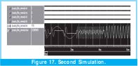
In Figure 17 can be observed a much more interesting simulation. As in the preceding first 4 signals, it does not show us any relevant information, due to its high frequency, but in the last two: the entry signal in purple and the exit signal in red show an interesting behavior. In first place , a low frequency signal was injected, in which having zero crossings a typical response to impulse within our filter is shown, which stabilizes in one semi-cycle of oscillation, which is a very good response, in the following segment, a high frequency signal is injected which is almost absolutely diminished, and by last a period of time in which a same frequency as the filter resonance is injected and which passes totally.
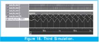
In Figure 18. A test is made running the filter sampling to a higher frequency, to demonstrate that the filter can work at much more higher frequencies, and being these frequencies of such a high level, the test is satisfactory, and being this test on the limit noting small deformations in the signal not being able to reconstruct the entry signal, this test was made with an entry signal that coincided with the new frequency of resonance of the filter.
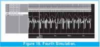
By last, in Figure 19, a test was made that tests in real terms the filter. In the entry signal was made a multiplication between the signal that corresponded the resonance frequency of the filter with white sound (pseudo aleatory signal), giving as result a signal visualized in yellow, a signal totally deformed but that implicitly has the frequency that makes the filter to react trying to reconstruct (in red) the original signal of adequate frequency for our purposes, is a test very significative, due to the system being able to reconstruct deformed signals by systematic and totally aleatory errors, which is hard to find in a filter an less in a digital one.
5. CONCLUSIONS
The development of the FIR digital filter, through the methodology described in this paper has allowed to realize a satisfactory digital solution in terms of response times, filtering selectivity, optimization of available hardware resources in the FPGA selected and in the time required for the development which was very reduced. The results obtained in the FIR filter tests, related to response times are very satisfactory, emphasizing the processing levels of the reconfigurable architectures.
REFERENCES
[1] ALTERA Corp., "FPGAs Provide Reconfigurable DSP Solutions", White Paper, August 2002, version 1.0.
[2] ALTERA Corp., "Implementing FIR Filters in FLEX Devices", Application Note 73, February 1998, version 1.01
[3] ALTERA Corp., "Using PLDs for High-Performance DSP Applications", White Paper, February 2002, version 1.0.
[4] G. Proakis and D. Manolakis. "Tratamiento digital de señales", Primera Edición, Prentice Hall. 1998.
[5] K. Ogata. "Sistemas de Control en Tiempo Discreto", Segunda Edición, Prentice Hall. 1996.
[6] LAHUERTA Aguilar, Eduardo; MEDRANO Sanchez, Carlos y RAMOS Lorente, Pedro, et al. Implementación de un filtro digital en VHDL. Universidad de Zaragoza, España.
[7] MELGAREJO, Miguel y PIRAJAN, Alexis, et al. Filtro FIR adaptativo sobre celdas lógicas programables FPGA. En revista Ingenieria, Universidad Distrital. Bogota, Colombia. 2000.
[8] R. Hamming. "Digital Filters", Editorial Prentice Hall. 1999.
[9] R. N Vera. "Sistemas de Transmisión", Segunda Edición, Mc Graw Hill. 1998.
[10] S. Haykin. "Señales y Sistemas". Primera Edición, Prentice Hall. 1997.
[11] VERA Lizcano, Mario; VEJARANO, Gustavo y Velazco Medina, Jaime, et al. Diseño de funciones DSP usando VHDL y CPLDs-FPGAs. En revista: Ingenieria y Competitividad, Universidad del Valle. Cali, Colombia. 2006.
[12] XILINX Corp., "Distribuited Arithmetic FIR Filter".Marzo 2002.
César Augusto Hernández Suárez
Nació en Villavicencio, Colombia. Es Ingeniero Electrónico de la Universidad Distrital F. J. C. de Bogotá, Colombia. Especialista en Interconexión de Redes y Servicios Telemáticos de la Universidad Manuela Beltrán. Magíster en Ciencias de la Información y las Comunicaciones de la Universidad Distrital, y actualmente adelanta estudios de maestría en Economía en la Universidad de los Andes. Actualmente se desempeña como Docente de planta en la Universidad Distrital F. J. C. en el área de los circuitos digitales y el procesamiento digital de señales. Lctsubasa@Gmail.com
Edwar Jacinto Gómez
Nació en Bogotá, Colombia. Es Ingeniero de Control de la Universidad Distrital F. J. C. de Bogotá, Colombia. Actualmente adelanta estudios de Maestría en Ciencias de la Información y las Comunicaciones de la Universidad Distrital y se desempeña como Docente en la Universidad Distrital F. J. C. en el área de Circuitos Digitales.edwarjg@hotmail.com
Octavio José Salcedo
Ingeniero de Sistemas de la Universidad Autónoma de Colombia. Magíster en Teleinformática de la Universidad Distrital. Magíster en Economía (PEG) de la Universidad de los Andes de Bogotá. Estudiante del Doctorado en Ingeniería Informática de la Universidad Pontificia de Salamanca, España. Se desempeña como Docente de la Facultad de Ingeniería de la Universidad Distrital y en la Universidad Nacional de Colombia. Es director del Grupo de Investigación "Internet Inteligente" de la Universidad Distrital. ojsalcedop@unal.edu.co
Creation date:
License
![]()
From the edition of the V23N3 of year 2018 forward, the Creative Commons License "Attribution-Non-Commercial - No Derivative Works " is changed to the following:
Attribution - Non-Commercial - Share the same: this license allows others to distribute, remix, retouch, and create from your work in a non-commercial way, as long as they give you credit and license their new creations under the same conditions.

2.jpg)